Assembly of the PlanktoScope kit🔗
Content of the Kit🔗
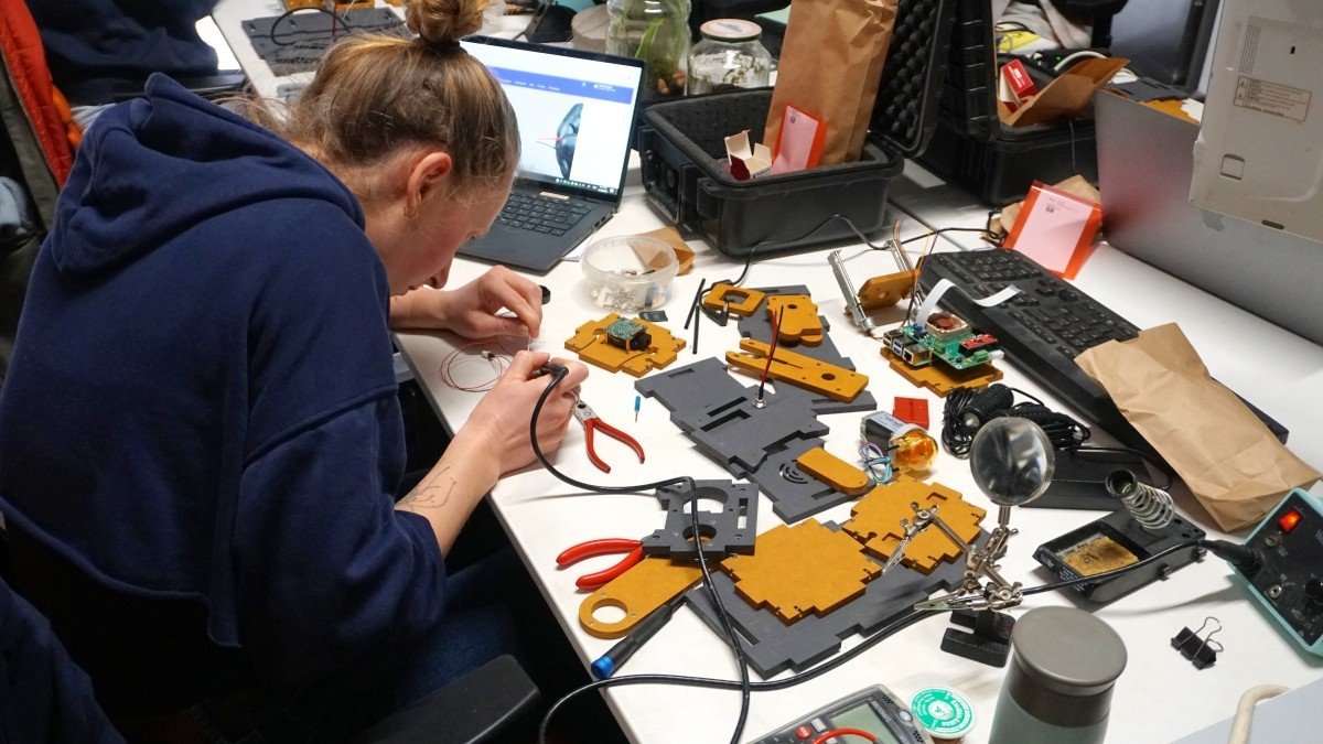
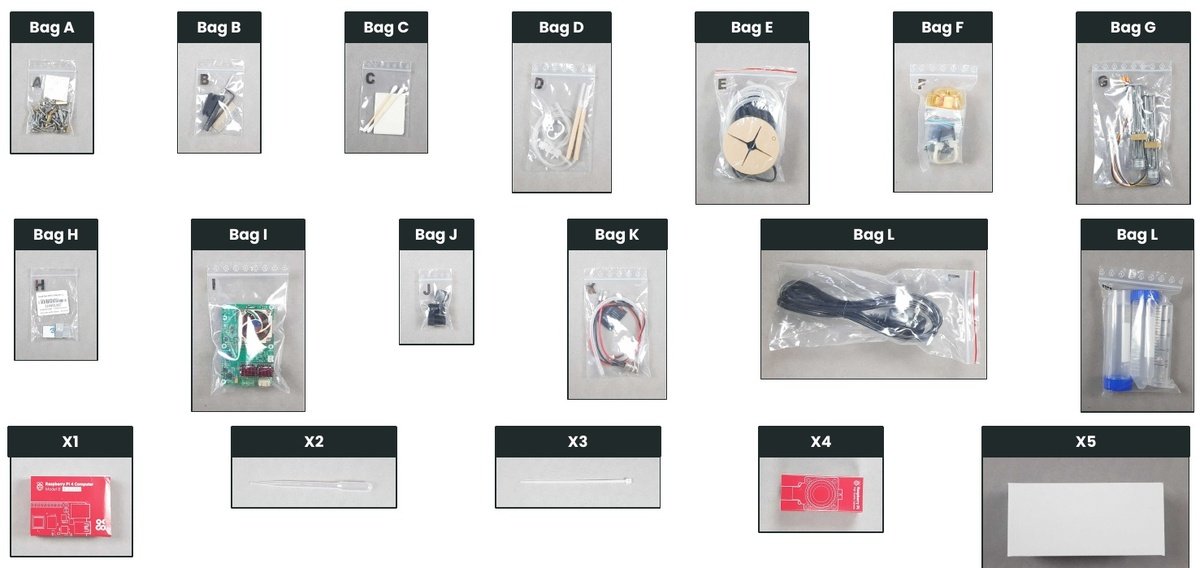
It is important to ensure that you have all of the necessary components before beginning the assembly of your PlanktoScope. To do so, please check that all bags are present as part of the kit.
| Bag | Content |
|---|---|
| A | Scews |
| B | Tools |
| C | Adhesive Pads |
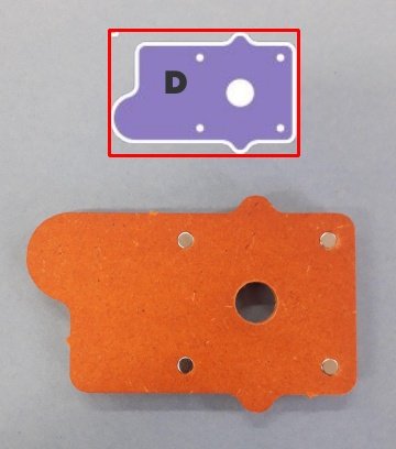
| D | Tubing, Glass Cuvettes |
| E | Bubbler Pump |
| F | Peristaltic Pump |
| G | Linear Stepper Motor |
| H | Raspberry PI Chip cooler |
| I | Raspberry HAT |
| J | Camera Lens |
| K | MicroSD Card, DC Power Jack Socket |
| L | DC Power Supply and Cable |
| M | Syringe and Falcon Tube |
| X1 | Raspberry PI 4 |
| X2 | Pipet |
| X3 | Cable ties |
| X4 | Raspberry PI HQ Camera Modul |
| X5 | Sandpaper |
If any bags are missing, please go back to the BOM (Bill of Materials) and reorder the required components.
About this document🔗
To read this document, follow these guidelines:
Color codes🔗
- 🔴 Look to the color red
- 🟠 Look to the color orange
- 🟡 Look to the color yellow
- 🟢 Look to the color green
- 🔵 Look to the color blue
- 🟣 Look to the color purple
Icons🔗
- 👁 Pay attention to this
- ⚠ Be careful with this
- 📜 The book says
- 🎬 Action !
- ❌ Don't focus on that location
As you read through the document, be sure to pay attention to these visual cues to guide you through the build process.
Requirements🔗
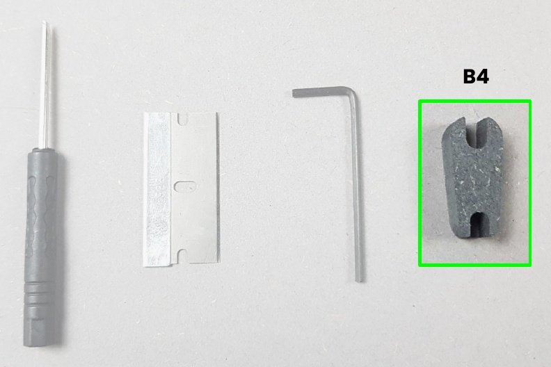
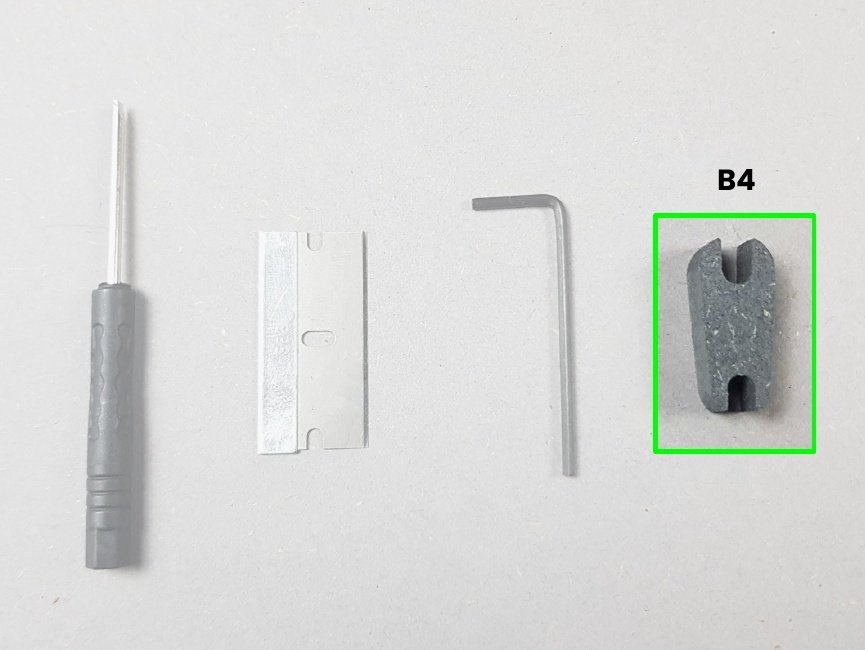
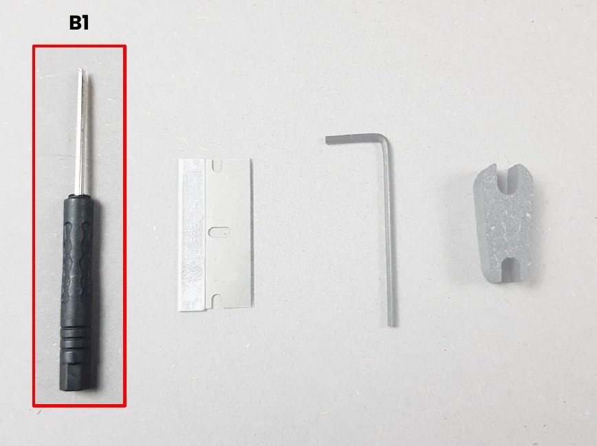
Tools🔗
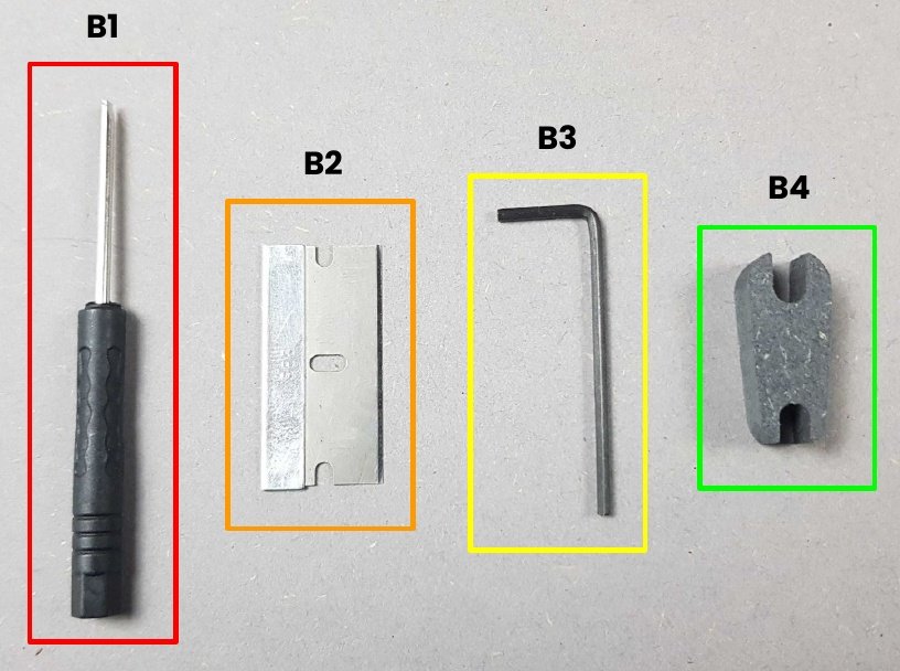
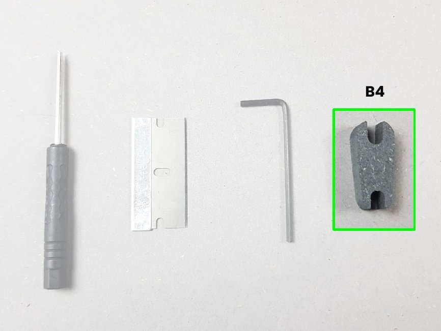
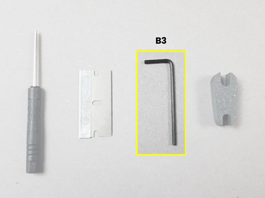
Content of Bag B:
- 🔴 B1. Small flat screwdriver 2mm
- 🟠 B2. Razor blade
- 🟡 B3. Allen key 2mm
- 🟢 B4. Wrenches for standoffs
Components🔗
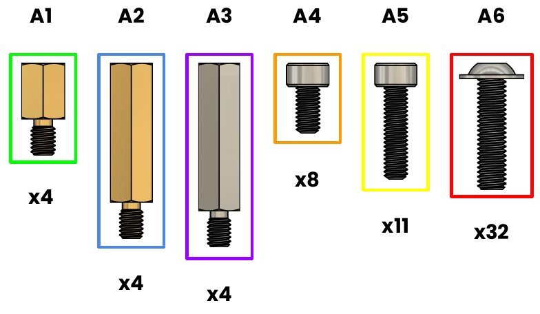
Content of Bag A:
- 🟢 A1. Standoff M2.5 - 6mm - Brass
- 🔵 A2. Standoff M2.5 - 15mm - Brass
- 🟣 A3. Standoff M2.5 - 16mm - SS
- 🟠 A4. Screw M2.5x5mm CHC - SS
- 🟡 A5. Screw M2.5x10mm CHC - SS
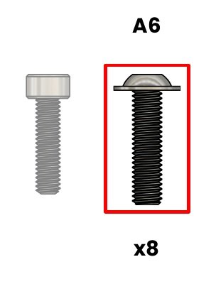
- 🔴 A6. Screw M3x12mm BHC - SS
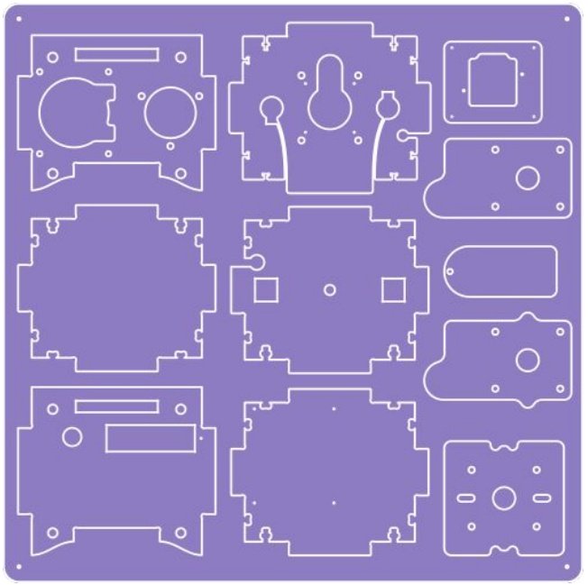
Chapter 1: Detach the Parts from panels by cutting the tabs🔗
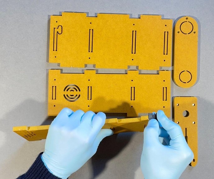
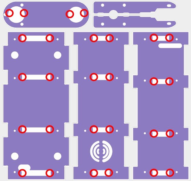
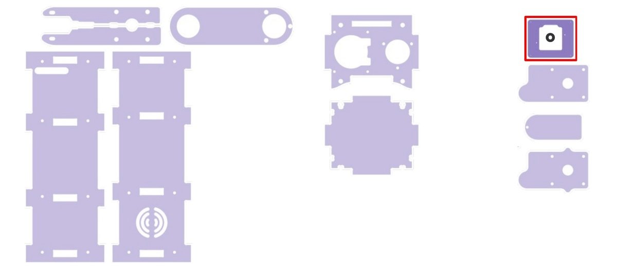
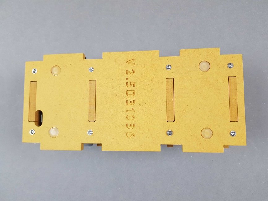
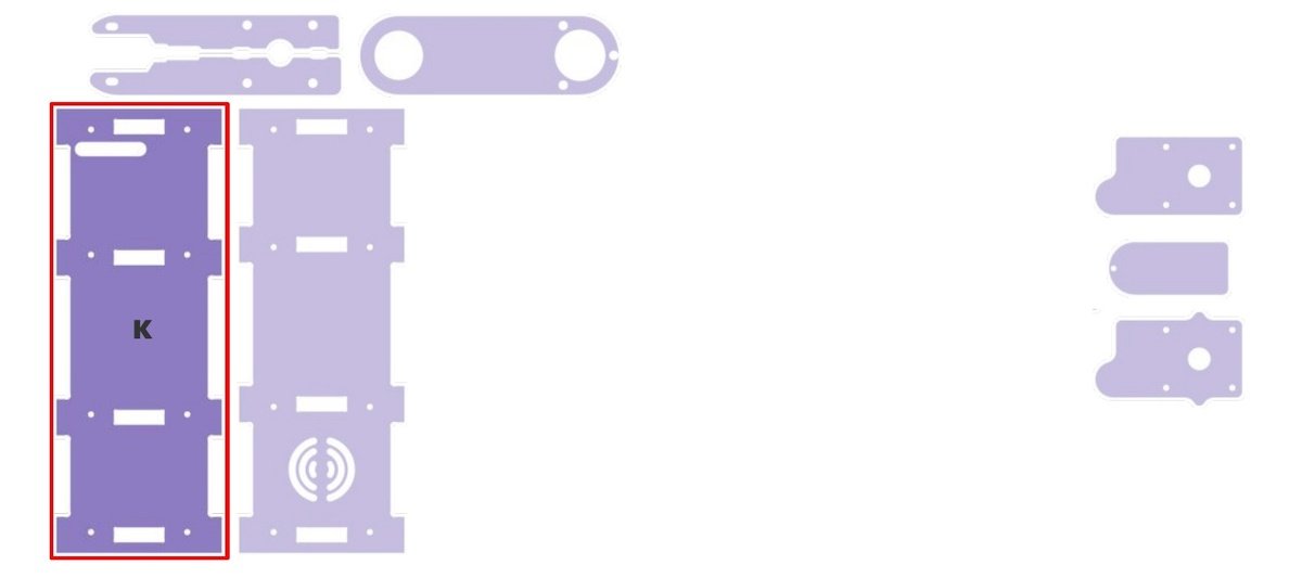
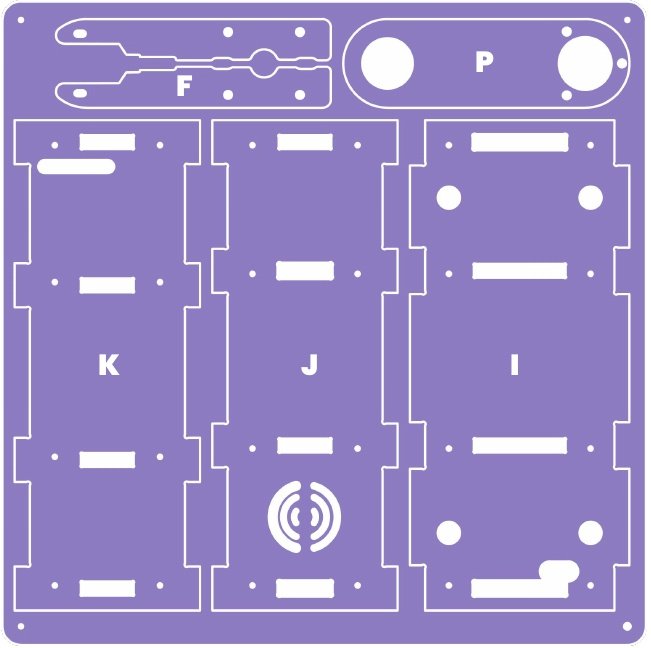 👁 Locate the panel S1 and discover the 5 differents Parts F, P, K, J and I.
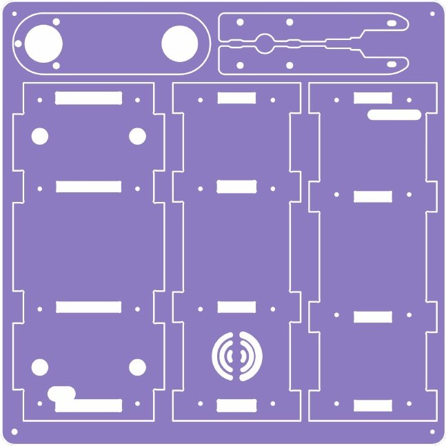 🎬 Flip your panel S1.
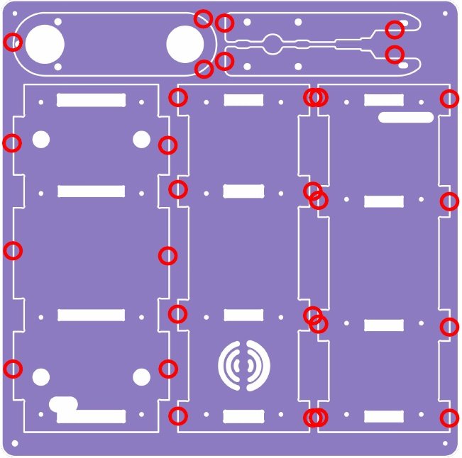 🔴 Locate the outer tabs on the edges of the different Parts. These are typically small projections of material that are used to secure the case parts to the panels.
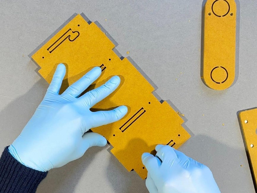
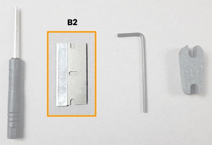 Gather all the necessary tools. You will need the B2 🟠 Razor blade to cut the tabs.
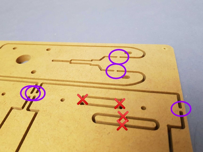
- 🟣 Use the razor blade to cut the outer tabs located on the edges of the different Parts
- ❌ Do not cut the inner tabs present inside the different Parts for now and focus on the outer tabs attaching the Parts to the main panel.
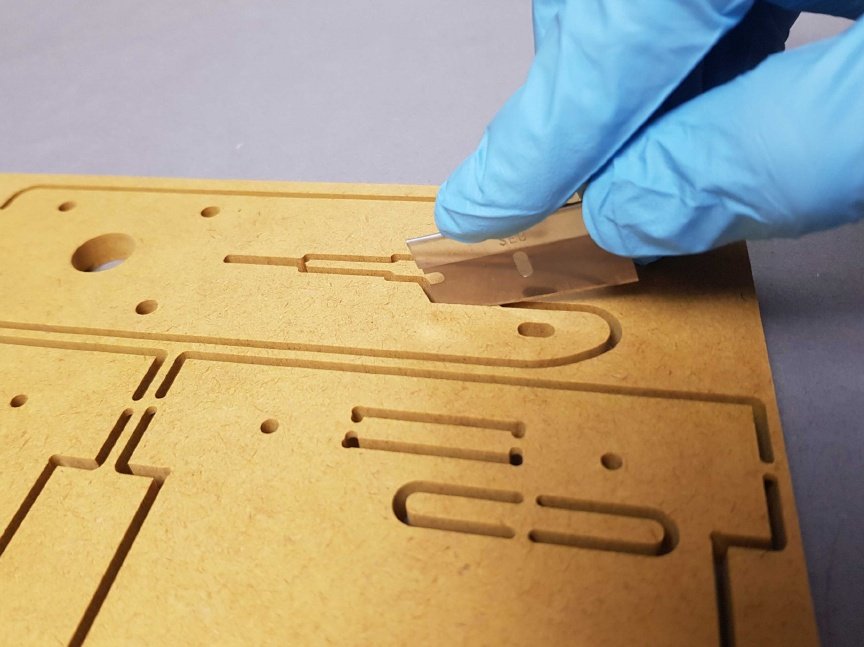
- Position your razor blade on the tab as close to the piece as possible to avoid residual tab after cutting.
- Press firmly on the razor blade, being very careful with your finger, to cut your first tab.
- Make sure you don't damage your table by placing a flat, rigid support under the S1 panel.
- Keep going with the other tabs of this piece F.
Once all of the tabs are cut, gently lift the case parts away from the panels. If the case parts are stuck or difficult to remove, you may need to gently wiggle or pry them loose using a flat tool such as a screwdriver.
Warning
Be extremely careful because this is very sharp.
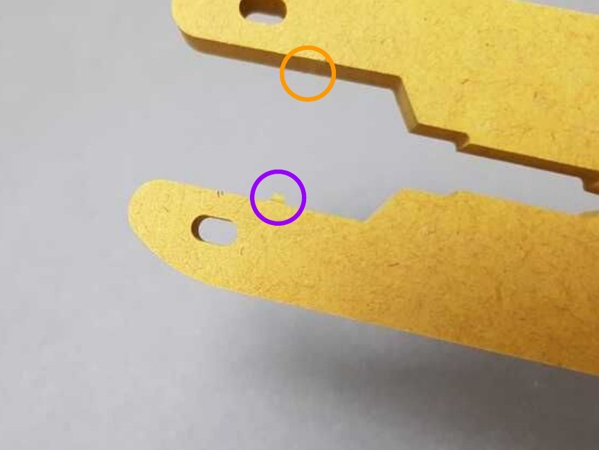
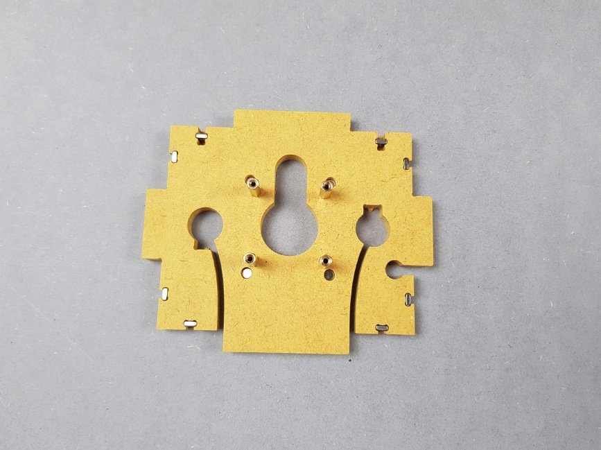
Once you have removed your Part from the main panel by cutting off all the tabs holding it, inspect it for potential residual tabs.
- 🟣 Here is a residual tab that will need to be removed.
- 🟠 Here there is no residual tab which is perfect.
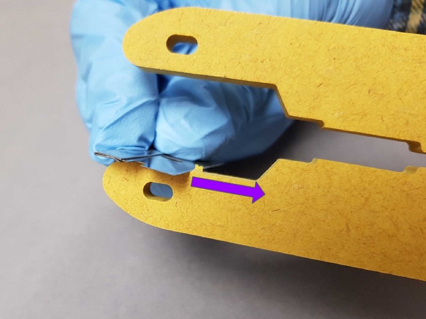
🟣 Place your razor blade flat on the edge of your piece being very careful with your fingers and cut the residual tab.
Warning
Be extremely careful because this is very sharp.
Repeat the cutting of the tabs on all the Parts F, P, K, J and I present on the panel S1.
Warning
Be extremely careful because this is very sharp.
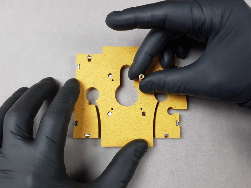
🔴 Locate the inner tabs on the edges of the different Parts.
Cut out the tabs inside of all the Parts F, P, K, J and I detached from the panel S1.
Dispose of the cut tabs and any other debris that may have been created during the detachment process.
Warning
Be extremely careful because this is very sharp.
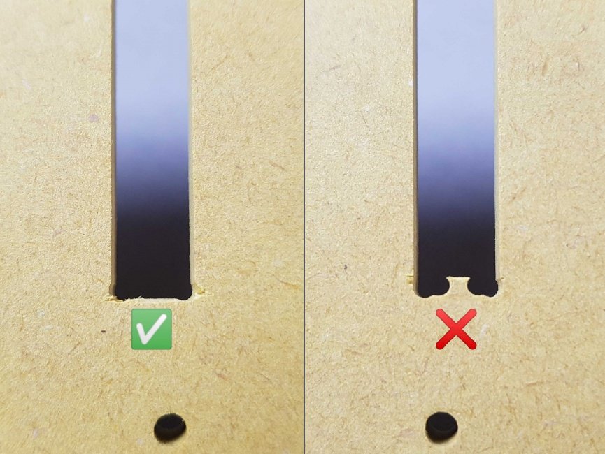
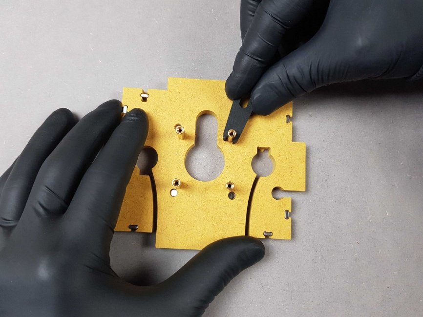
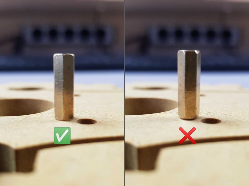
- ✅ Good way of cutting inner tabs
- ❌ Wrong way of cutting inner tabs
Repeat the process on the panel S2.
Warning
Be extremely careful because this is very sharp.
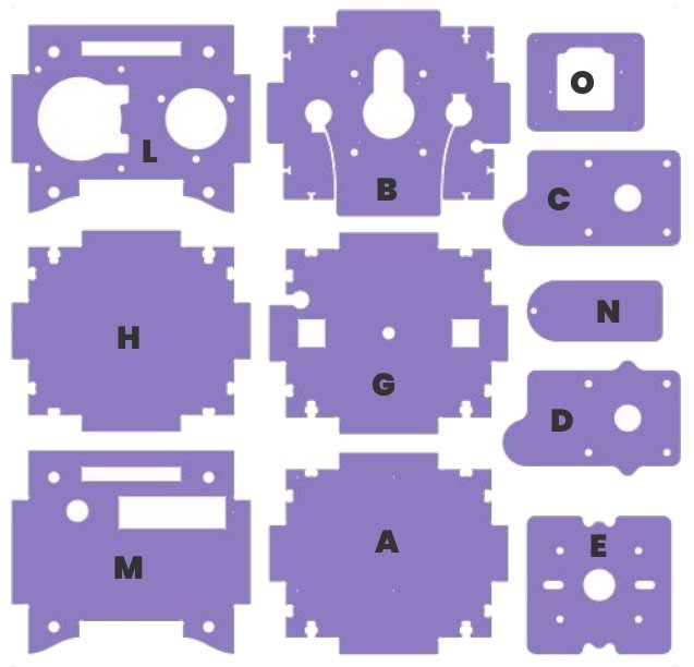
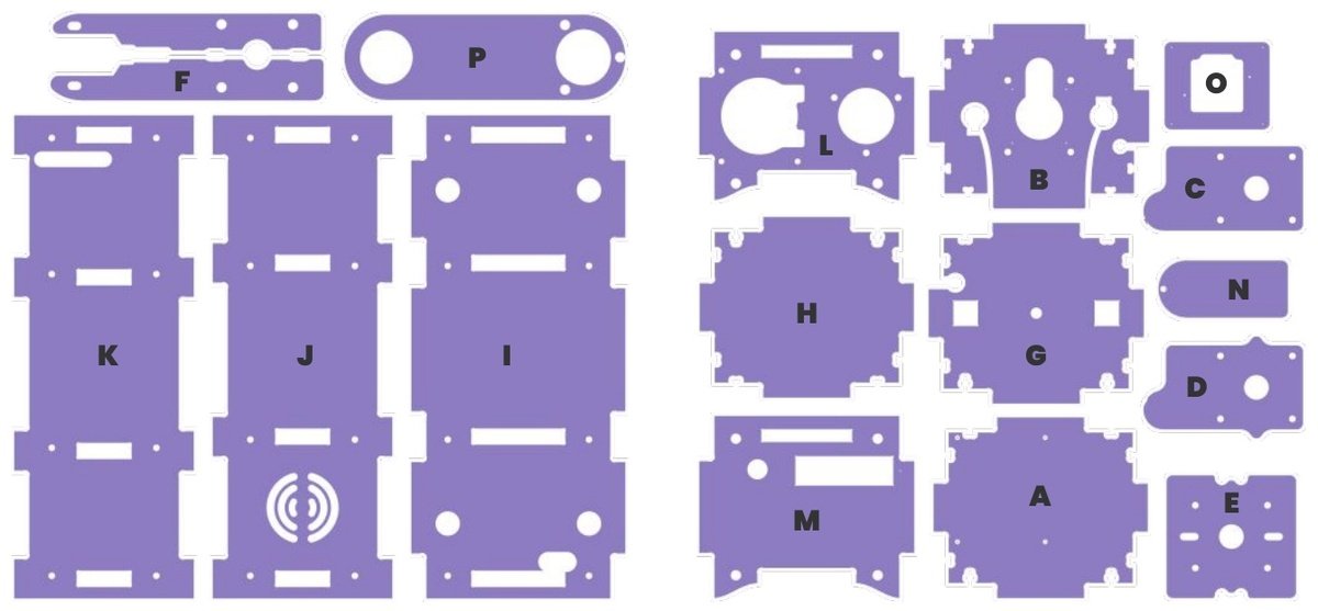
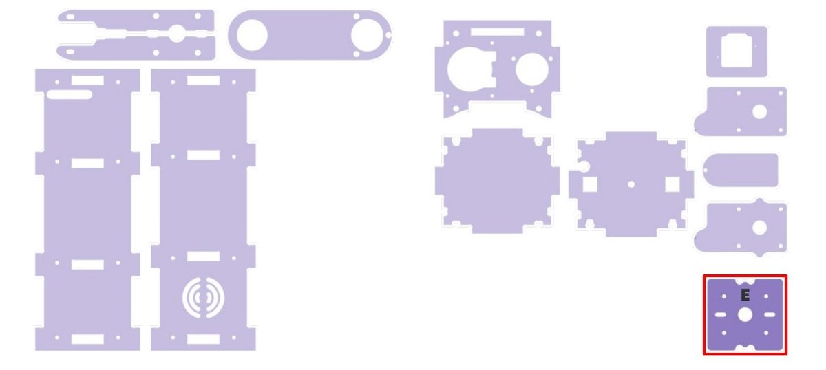
Discover the 11 differents Parts.
Dispose of the cut tabs and any other debris that may have been created during the detachment process. Inspect the case parts and panels for any damage or imperfections that may have occurred during the detachment process. If any damage is found, it may be necessary to repair or replace the affected parts.
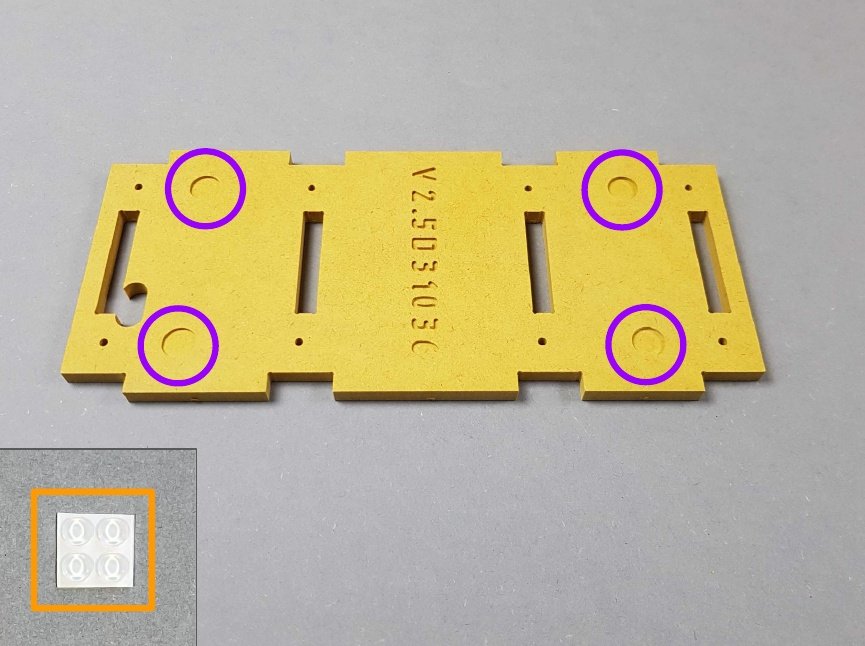
Chapter 2: Place the 4 Adhesive Pads under the Part I🔗
 To secure the PlanktoScope on slippery grounds using the adhesive pads, follow these steps. Gather all the necessary materials. You will need:
- Time: 1 min
- 👁 and Take the Part I
- 🟠 Take the four adhesive pads present in the bag A.
- 🟣 Locate the four pockets that will receive the four adhesive pads.
- Clean the bottom of the case part I. Make sure the surface is free of dirt, debris, and any other substances that may prevent the adhesive pads from sticking properly.
- Remove the paper and place the four adhesive pads in the pockets by pressing firmly on them, sticky-side down.
- Test the stability of the PlanktoScope by gently shaking or tilting it. If it feels secure and does not slip or slide, the adhesive pads have been successfully installed.
Note
🎬 Store this assembly for later.
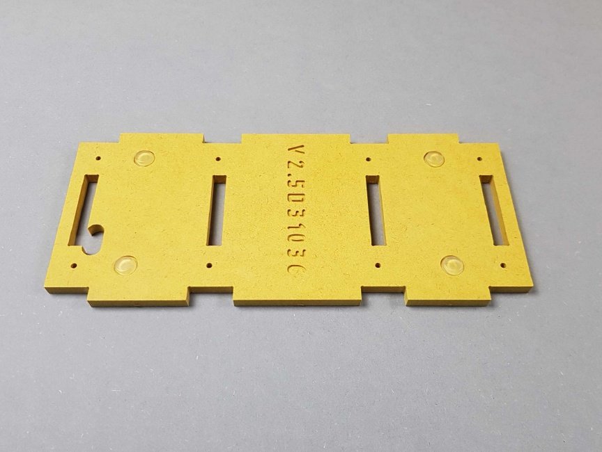
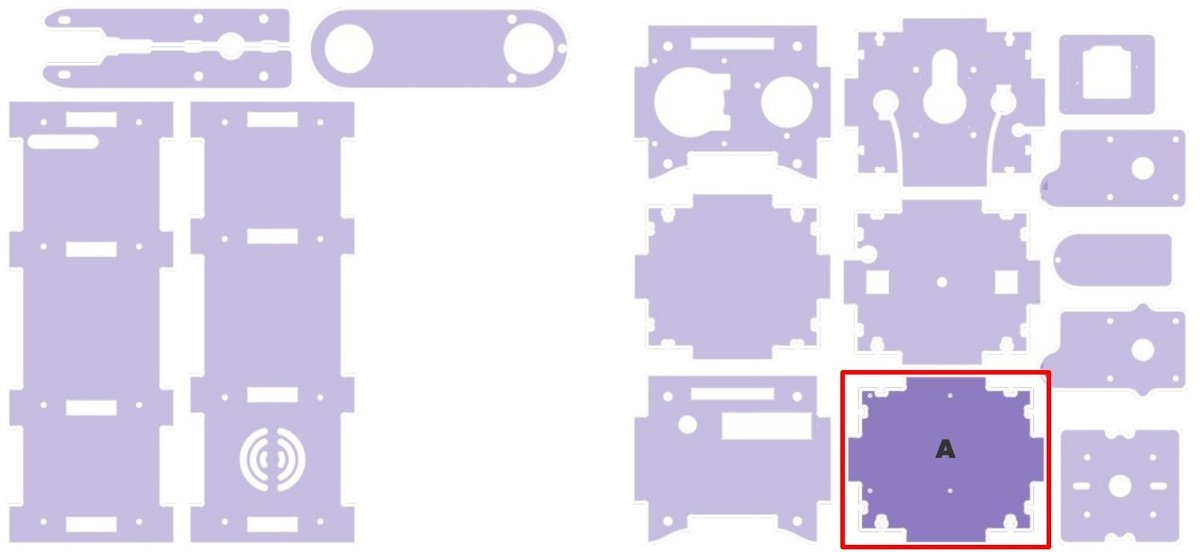
Chapter 3: Screw the four Standoffs into Part A🔗
Now it's time to assemble the ground plate for the Raspberry Pi as the PlanktoScope main processing unit.
- Time: 5 min
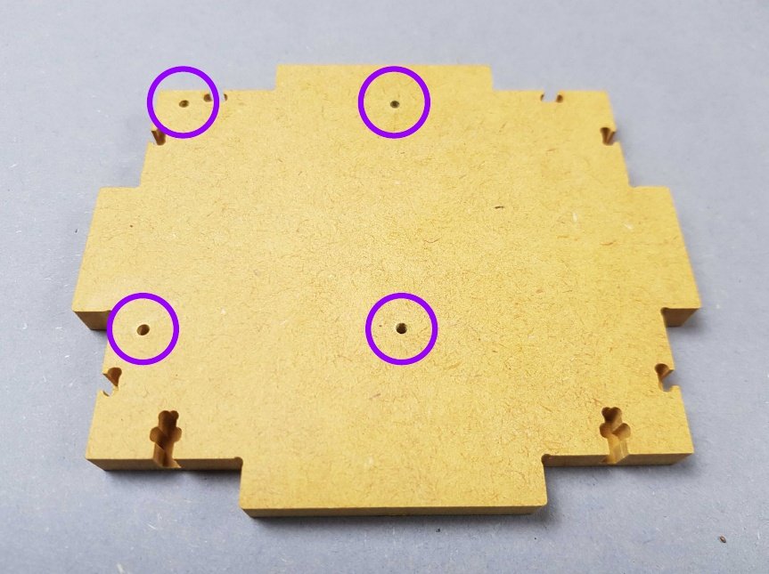
- 👁 Grab the Part A.
- 🟣 Locate the four holes on Part A.
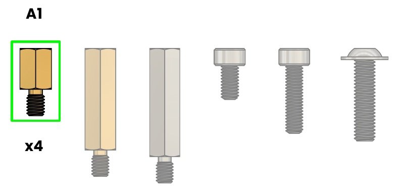
🟢 A1. Standoff M2.5 - 6mm- Brass
🟢 B4. Wrenches for standoffs
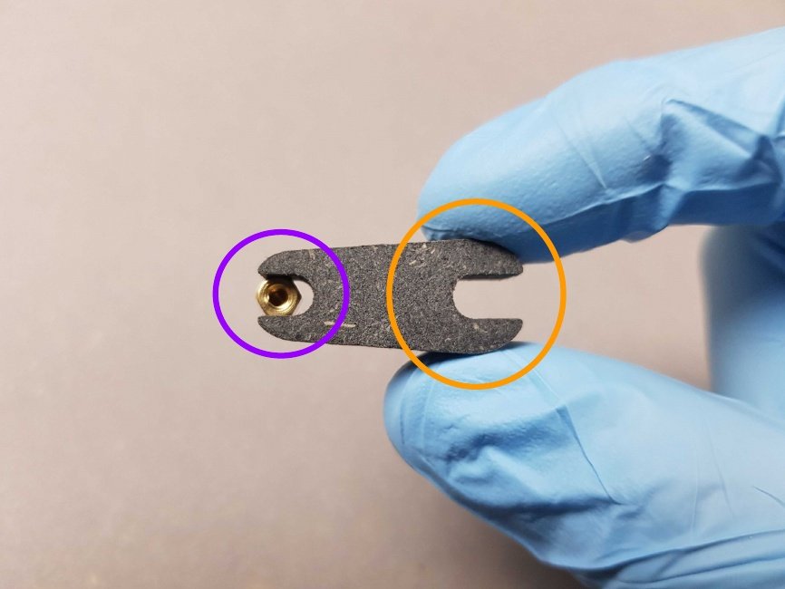
- 🟣 Place the Standoff M2.5 - 6mm in the small side of the wrenches for standoffs B4.
- 🟠 Do not use the big side of the wrenches for standoffs since the standoff will be loose in it.
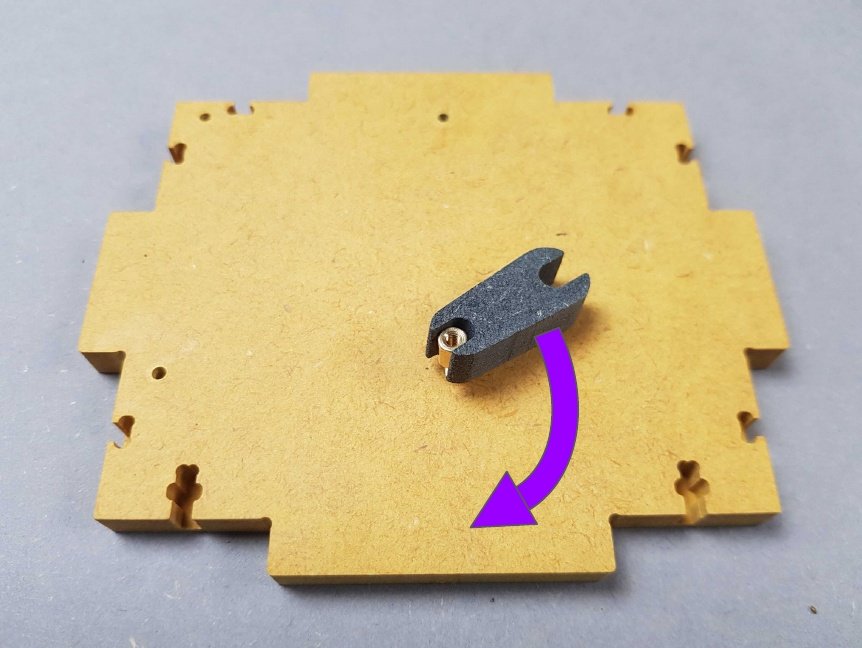
- Place the standoff in the hole and start rotating by hand in a clockwise direction until secure.
- Then tighten with the wrench.
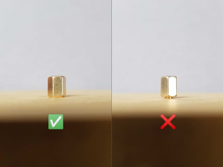
- ✅ Make sure to screw until the standoff is properly inserted in the hole.
- ❌ Do not stop screwing before.
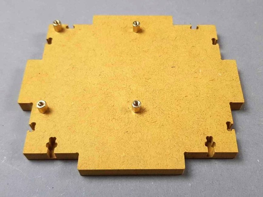
Keep going for each of the four holes.
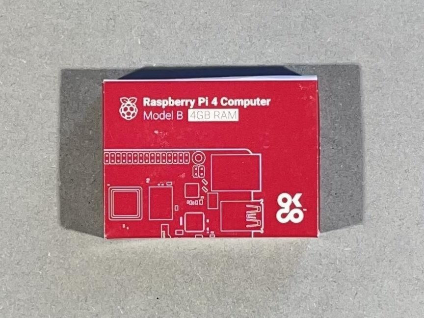
Chapter 4: Mount the Heat Sinks on the Raspberry Pi🔗
- Time: 2 min
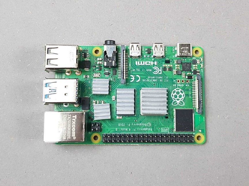
Locate the Raspberry Pi 4 Model B packaging.
Warning
Be careful removing it from its packaging.
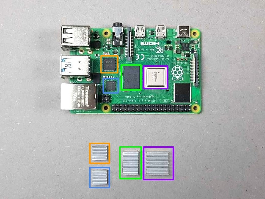
Place the four Heat Sinks next to your Raspberry Pi and mark the locations of the Heat Sinks on the Raspberry Pi.
- 🟠 & 🔵 Small Heat Sinks
- 🟢 Medium Heat Sink
- 🟣 Big Heat Sink
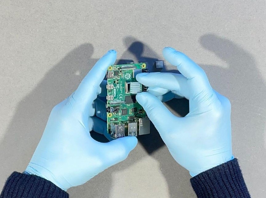
Remove the protective labels under a Heat Sink and place the Heat Sink on the slot of the Raspberry Pi.
Remove the protective labels under all the Heat Sinks and place all the Heat Sinks on the slots of the Raspberry Pi.
Chapter 5: Insert the micro SD card in the Raspberry Pi🔗
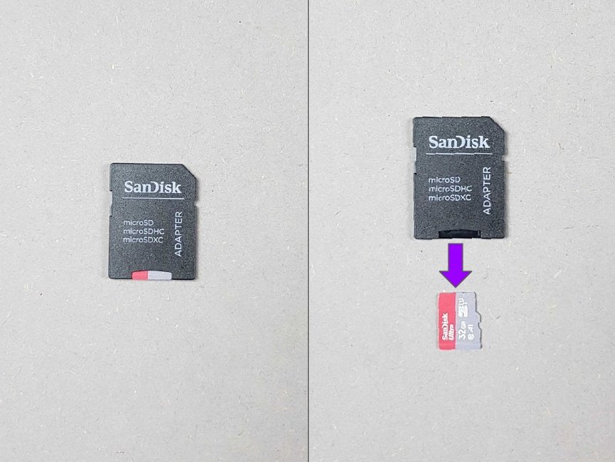
- Locate the SD card adapter in the bag K.
- The micro SD card is inserted in the SD card adapter.
- 🟣 Remove the micro SD card from the SD card adapter.
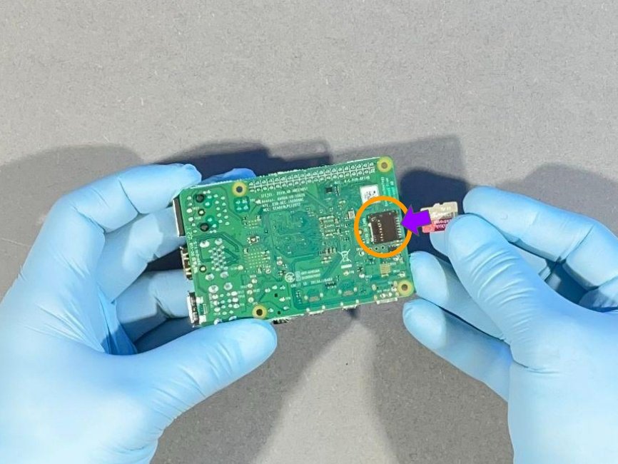
- Flip your Raspberry Pi.
- 🟠 Locate the micro SD port.
- 🟣 Insert the micro SD card in the Raspberry Pi.
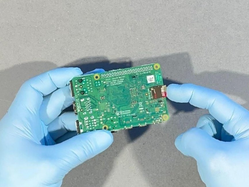
Push the micro SD card in the Raspberry Pi port to a point of resistance.
Note
If you notice that the micro SD card protrudes about 2mm from its slot, this is normal.
Chapter 6: Mount the Raspberry Pi on the Part A🔗
- Time: 1 min
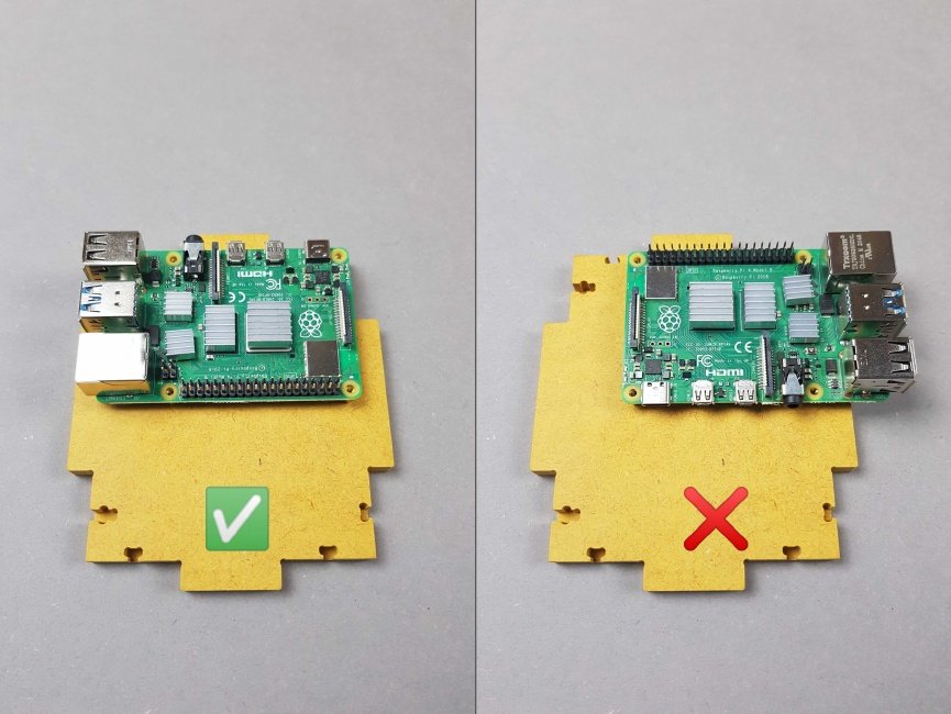
- ✅ Make sure to position the Raspberry Pi properly on the four standoffs screwed on the Part A.
- ❌ Do not invert the position of the Raspberry Pi on the four standoffs screwed on the Part A.
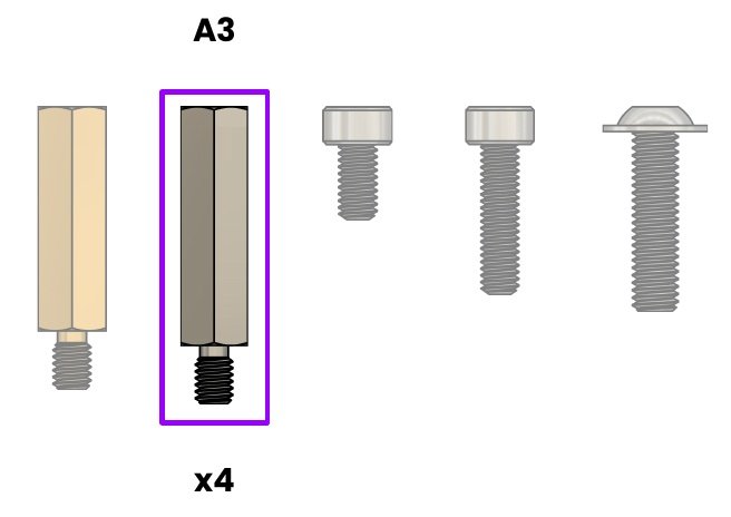
🟣 A3. Standoff M2.5 - 16mm - SS
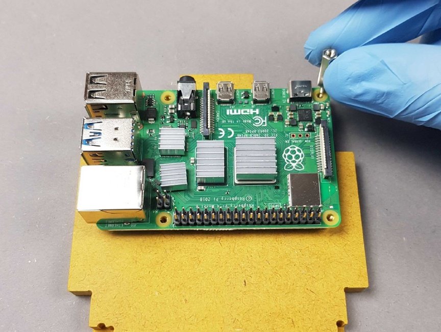
Screw by hand a Standoff M2.5 - 16mm on the Raspberry Pi.
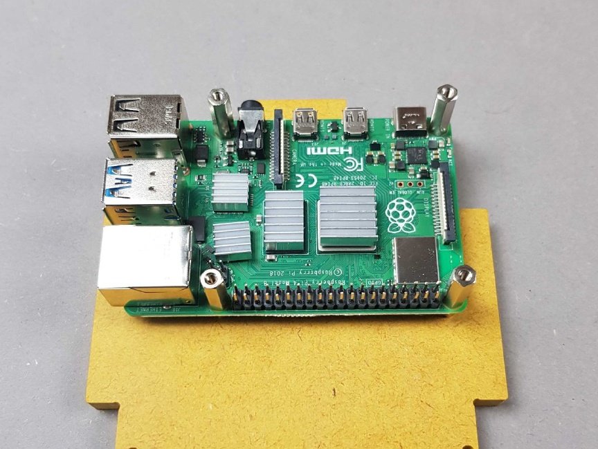
- Screw by hand all Standoffs M2.5 - 16mm on the Raspberry Pi.
- Make sure you insert all four standoffs by hand and tighten slightly.
🟢 B4. Wrenches for standoffs
- 🟠 Secure the Standoff M2.5 - 16 mm - SS A3 in the big side of the wrenches for standoffs B4.
- 🟣 Do not use the small side of the wrenches for standoffs since the standoff won’t fit in it.
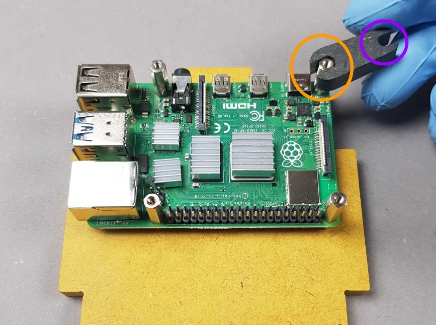
Chapter 7: Attach the Ribbon Cable to the Raspberry Pi🔗
- Time: 2 min
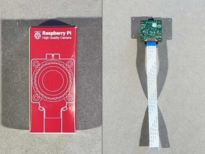
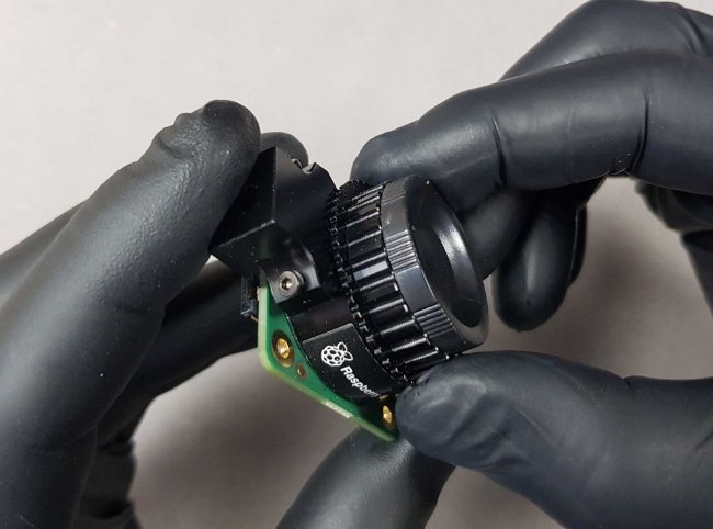
Locate the Raspberry Pi Camera HQ packaging.
Warning
Be careful removing it from its packaging.
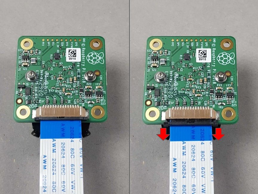
Lay your Raspberry Pi Camera face down on a suitable surface.
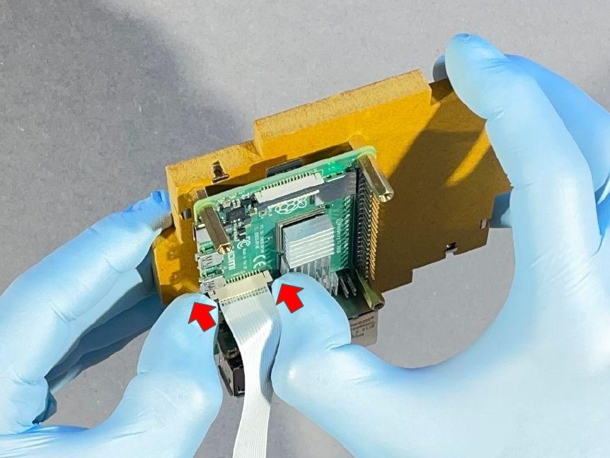
🔴 The black connector is simply a push/pull fit. To disengage the cable, pull the two corners of the black connector down, away from the camera board. It will unclip to about 3mm, make sure you don't pull it off! If you're struggling, try pulling off one corner of the connector at a time.
Warning
Be careful with this, this part is delicate. Lift the black connector gently
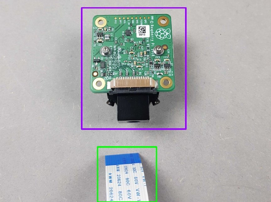
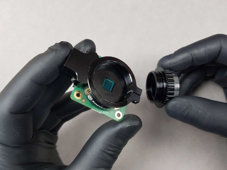
Once the connector has been disengaged from the Raspberry Pi camera board, the cable will simply slide out!
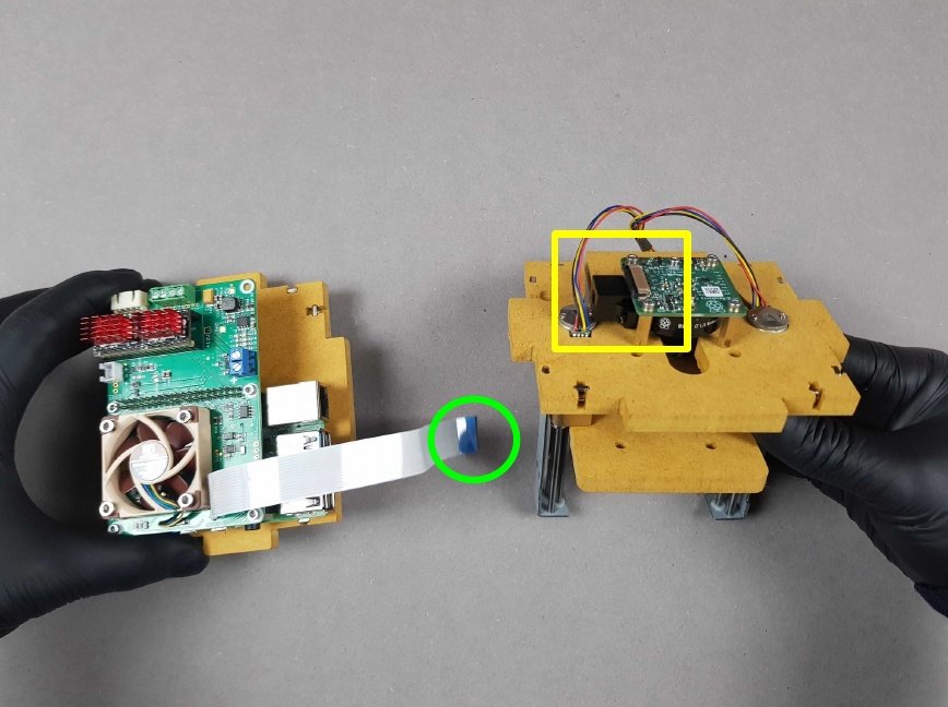
- 🟣 Put aside Camera the Raspberry Pi
- 🟢 Keep the Ribbon Cable for next step.
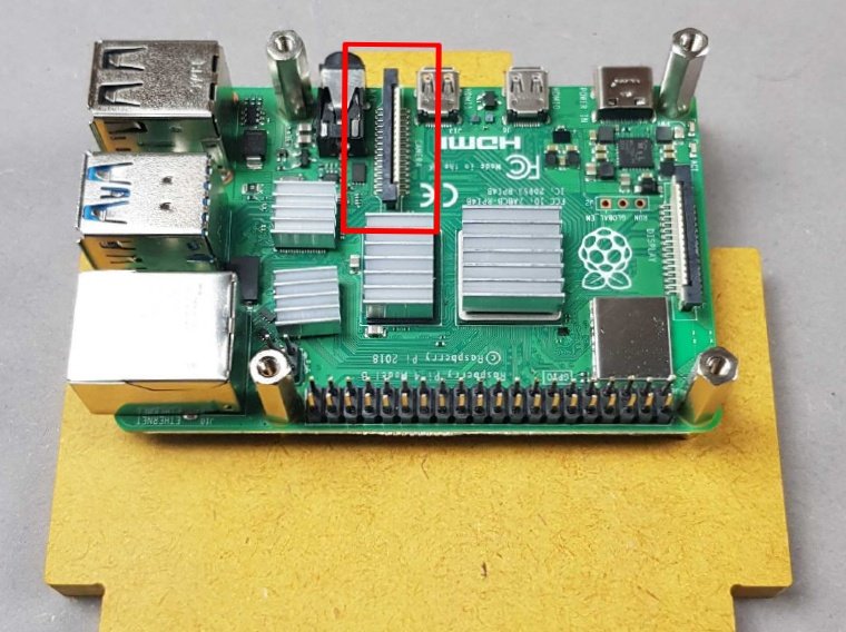
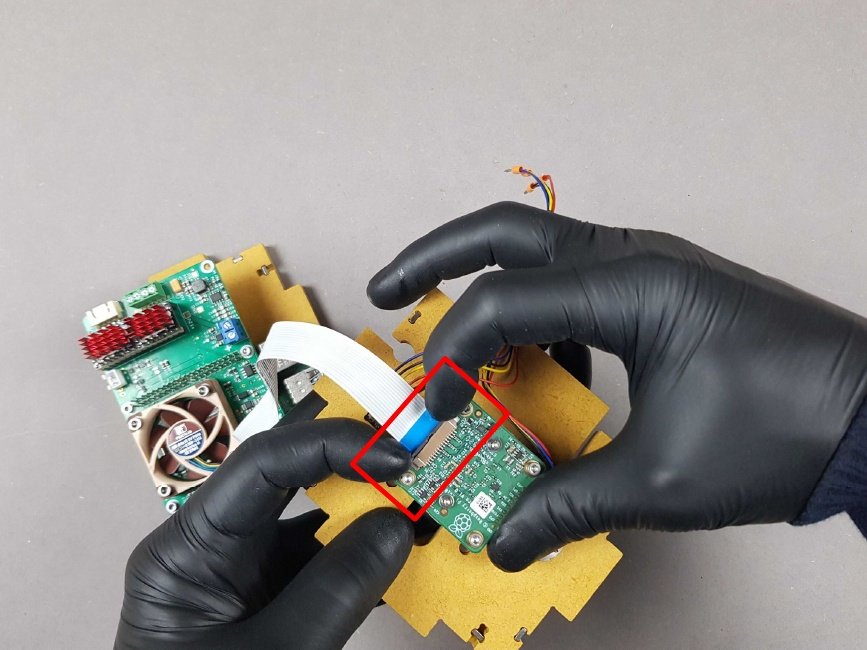
🔴 Locate the black connector present on the Raspberry Pi.
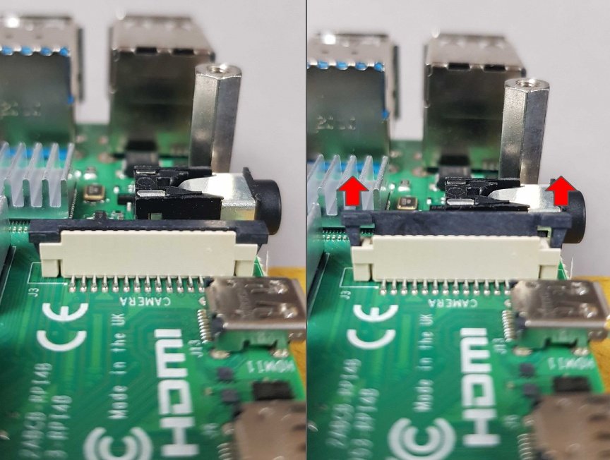
🔴 The black connector is simply a push/pull fit. To disengage the cable, pull the two corners of the black connector down, away from the camera board. It will unclip to about 3mm, make sure you don't pull it off! If you're struggling, try pulling off one corner of the connector at a time.
Warning
Be careful, this part is delicate. Gently prise the black connector with nail or fingertip and thumb.
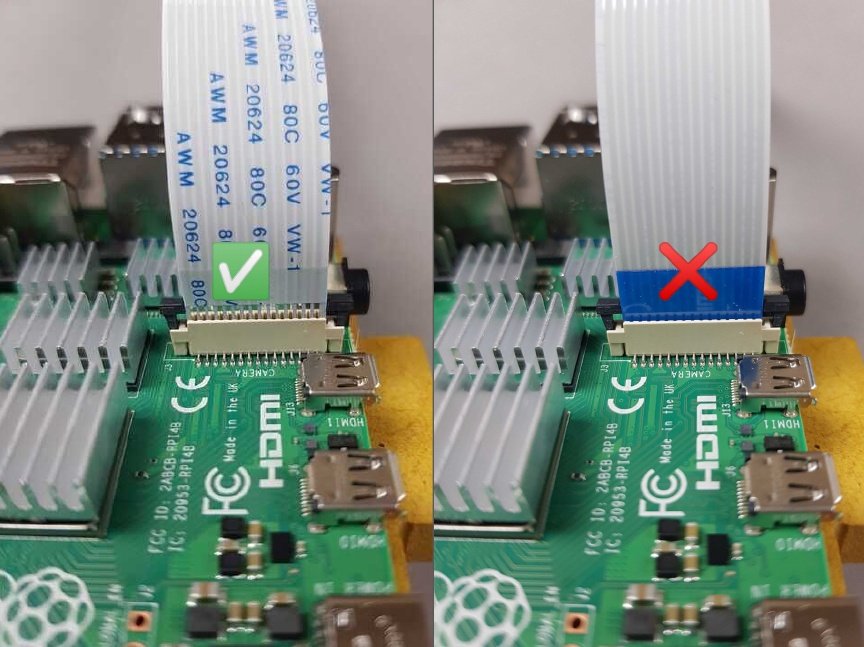
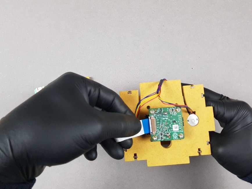
Insert the Ribbon Cable you just detached from the Raspberry Pi Camera in the Raspberry Pi.
- Make sure to insert in as much as you can.
- Blue rectangle on Ribbon Cable should face the same direction as the arrow below.
🔴 Secure the Ribbon Cable in the Raspberry Pi by pressing firmly on the black connector.
Chapter 8: Mount the PlanktoScope HAT on the Raspberry Pi🔗
- Time: 2 min
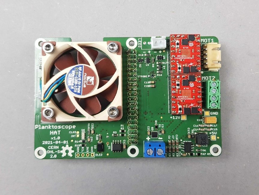
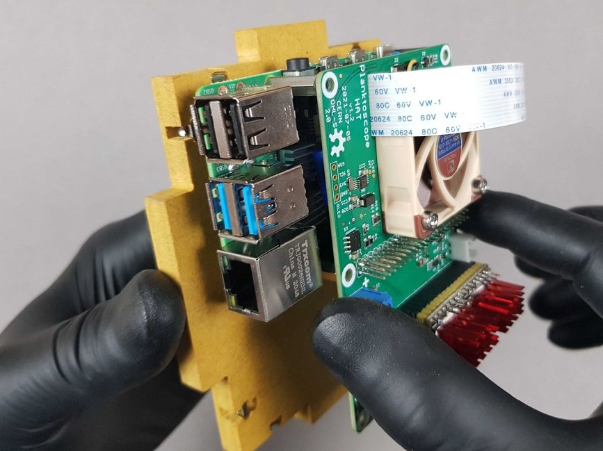
Locate the PlanktoScope HAT present in bag I.
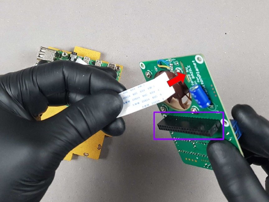
🔴 Thread the Ribbon cable through the PlanktoScope HAT slot from the underside.
Warning
Make sure the two 🟣 black connectors are aligned before threading through the ribbon.
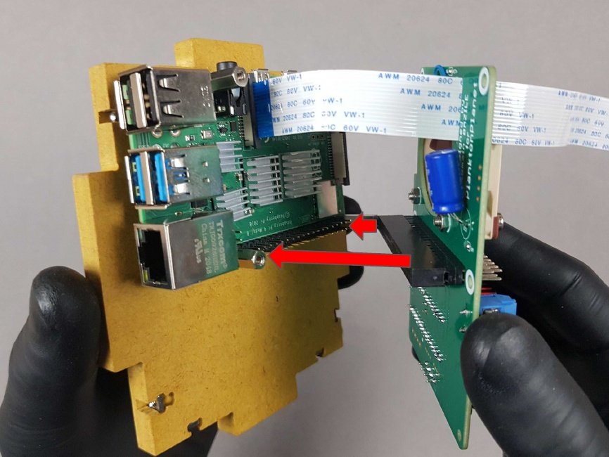
🔴 Plug the PlanktoScope HAT into the Raspberry Pi.
Warning
Make sure the two black connectors are aligned before attaching them together.
Press the PlanktoScope HAT against the Raspberry Pi until it is no longer possible to move them closer together.
Warning
Continue to feed through the Ribbon Cable and do not crush it while pressing the PlanktoScope HAT against the standoffs.
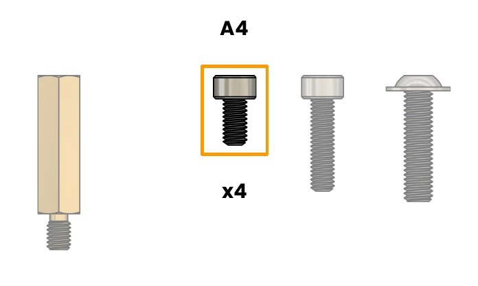
🟠 A4. Screw M2.5X5mm CHC - SS
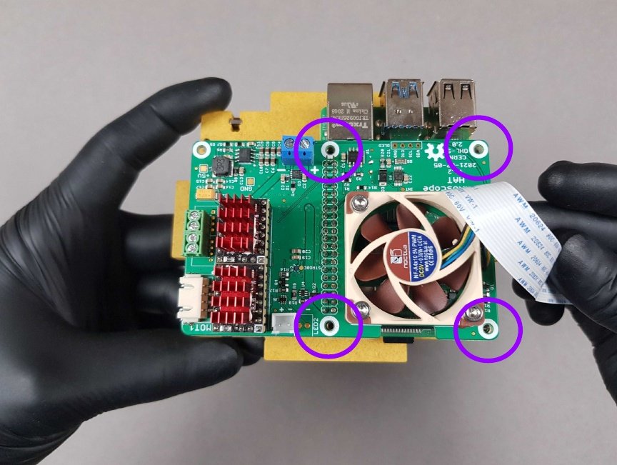
🟣 Locate the 4 holes on the top of the PlanktoScope HAT and insert the four M2.5X5mm

🟡 B3. Allen key 2mm
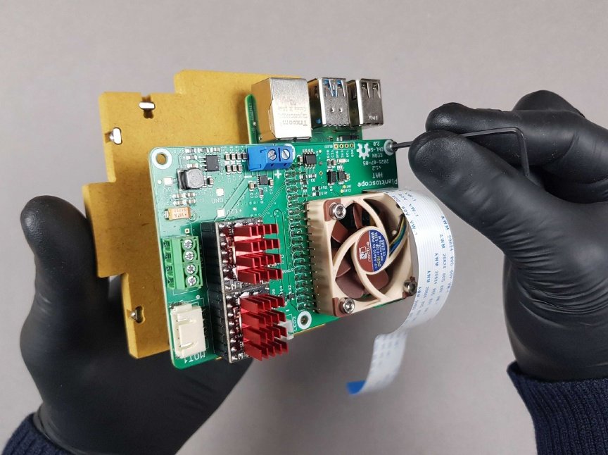
Screw the four A4 screws through the PlanktoScope HAT onto the Standoff M2.5 - 16mm.
Note
🎬 Store this assembly for later.
Chapter 9: Place the Power Socket on Part M🔗
- Time: 2 min
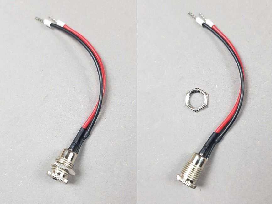
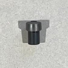
- Locate the DC Power Jack from the Bag K.
- Remove the Lock Ring from the DC Power Jack
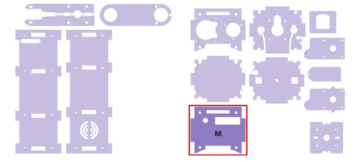
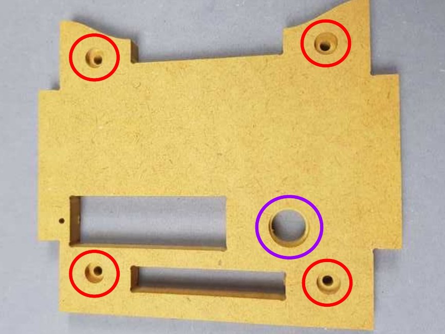
- 🔴 Lay the Part M down and make sure the pockets in these holes are facing upwards.
- 🟣 Locate the Power Socket hole on Part M.
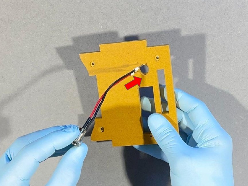
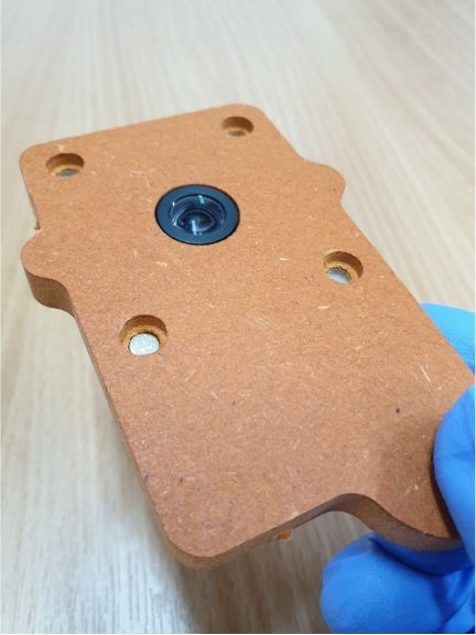
🔴 Insert the cable inside of the hole by being sure of the orientation of the Part M.
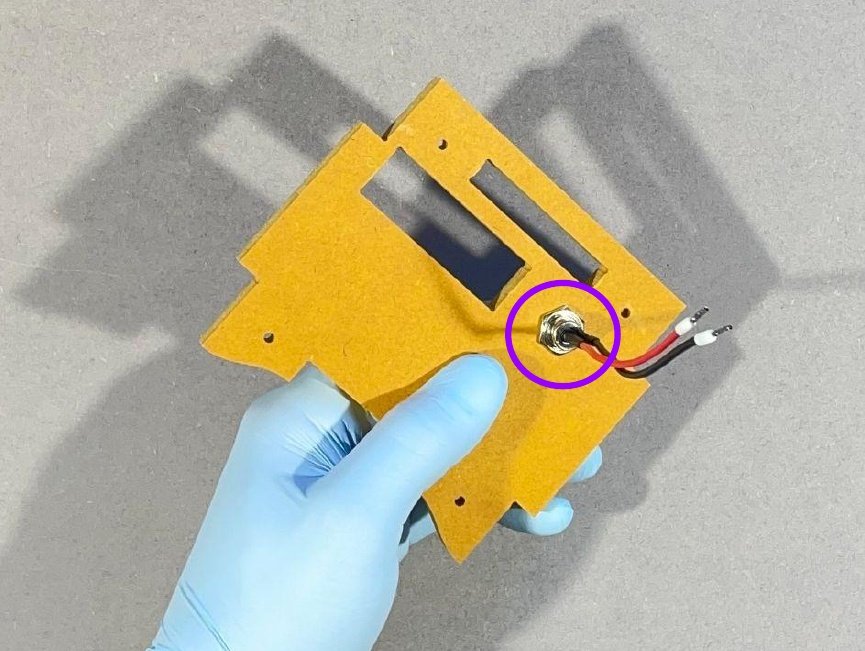
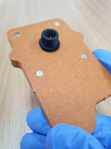
🟣 Flip the Part M and secure the DC Power Jack by hand on the Part M by screwing the Lock Ring.
Warning
Make sure the Lock Ring doesn’t spin on itself.
Note
🎬 Store this assembly for later.
Chapter 10: Mount the Raspberry Pi Camera HQ on Part B🔗
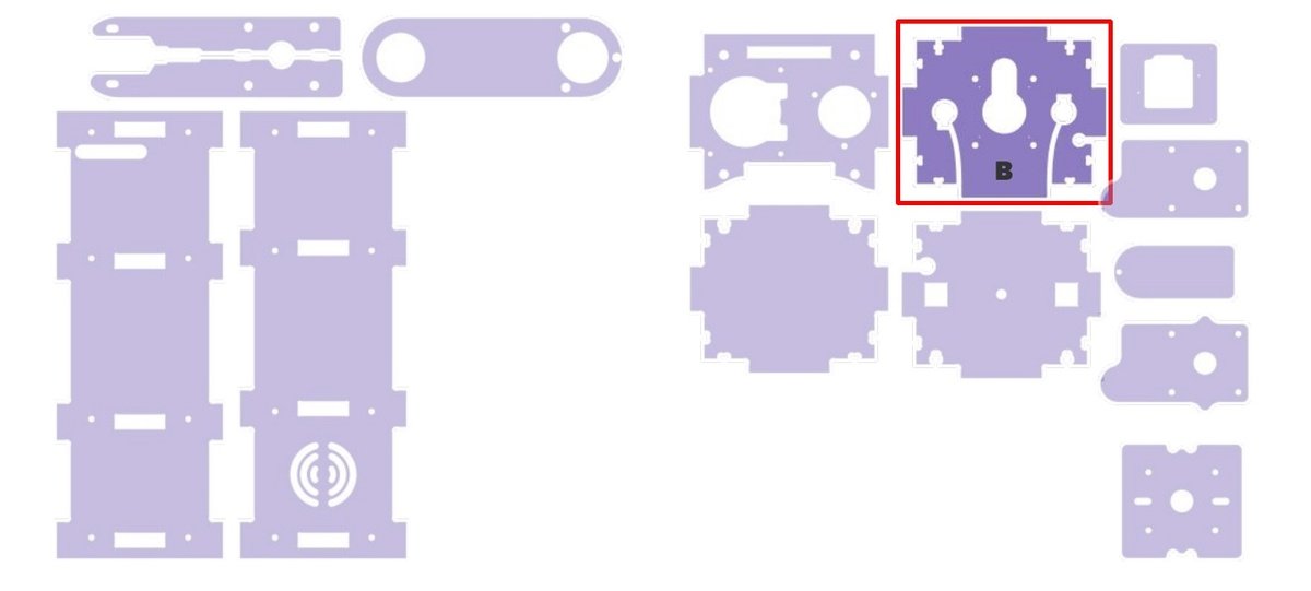
- Time: 2 min
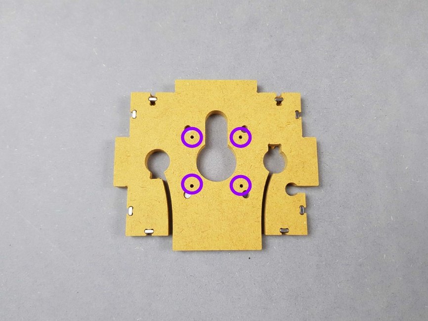
🟣 Locate the 4 holes on the top of the Part B.
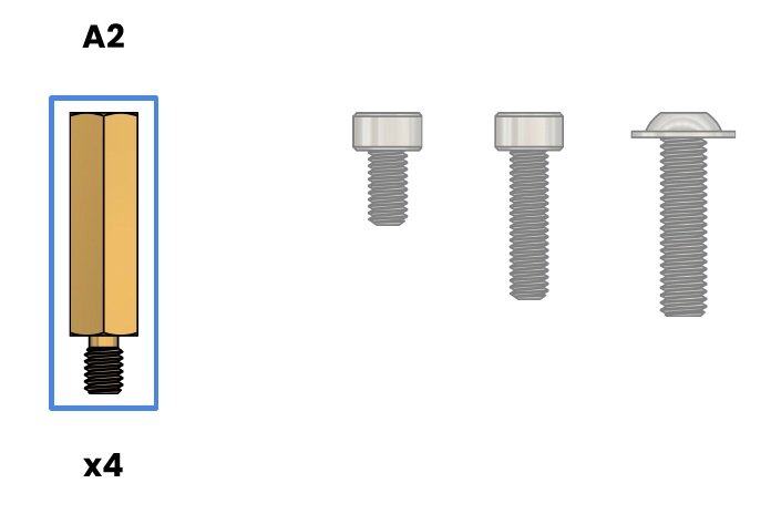
🔵 A2. Standoff M2.5 - 15mm - Brass
Insert the four Standoff M2.5 - 15mm.
The result should be similar to the picture.
🟢 B4. Wrenches for standoffs
Using the small side of the Standoff Wrench, secure the 4 M2.5 - 15mm Standoffs
- ✅ Make sure to screw until the Standoff is properly tightened into the hole.
- ❌ Do not stop screwing before.
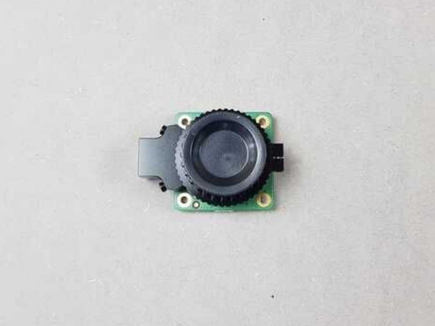
Locate the Raspberry Pi Camera HQ
Remove the lens cap Raspberry Pi Camera HQ.
Warning
Make sure your camera lens is clean. If it is not, gently wipe using cotton swab for this task.
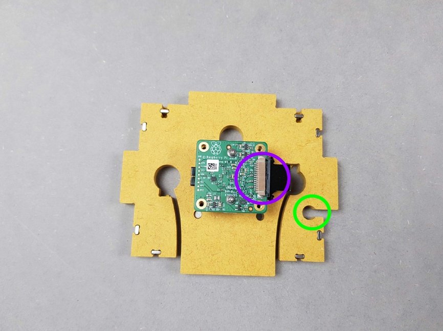
Place the Raspberry Pi Camera HQ on top of the four Standoffs installed on Part B.
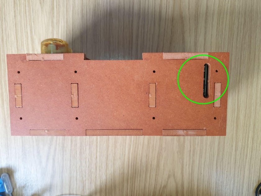
🟣Ensure correct orientation of the Raspberry Pi Camera HQ. The black connector where the Ribbon Cable was removed is on the same side as the 🟢slot circled in green
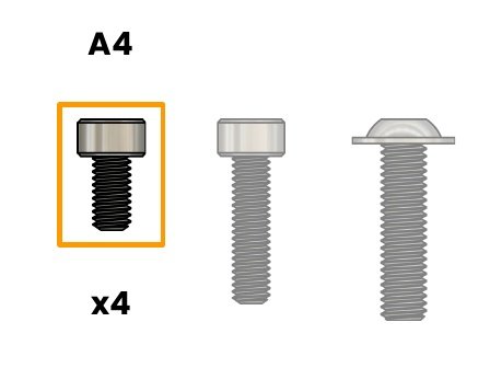
🟠 A4. Screw M2.5X5mm CHC - SS
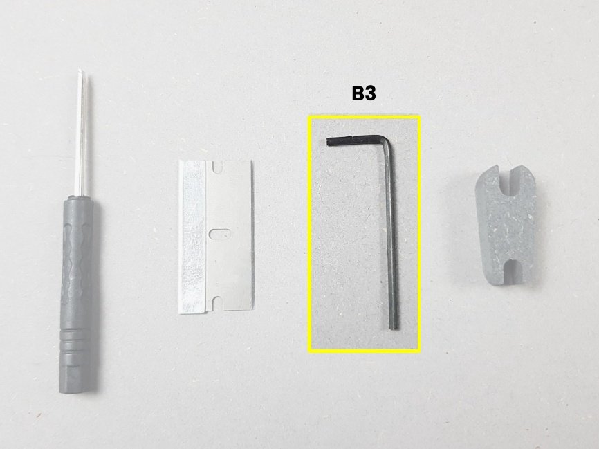
🟡 B3. Allen key 2mm
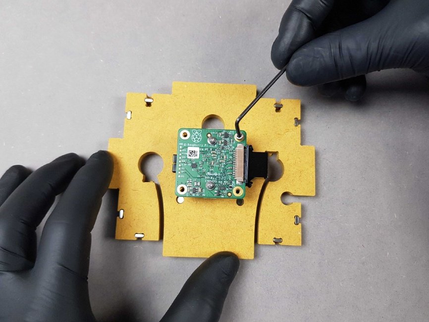
Use the allen key and tighten the Raspberry Pi Camera to the Standoffs.
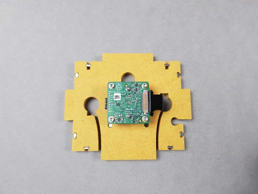
The result should be similar to the picture.
Note
🎬 Store this assembly for later.
Chapter 11: Mount the Linear Stepper Motor on Part E🔗
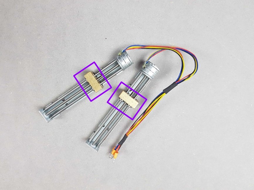
Locate the Stepper Motors
Warning
Avoid touching the metal rods on the Stepper Motors
Info
You can touch the 🟣 gold stands
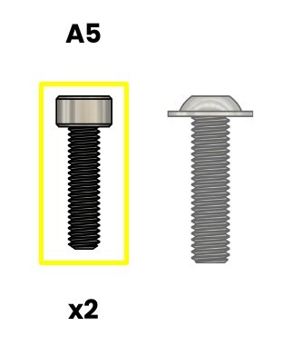
🟡 A5. Screw M2.5X10mm CHC - SS

🟡 B3. Allen key 2mm
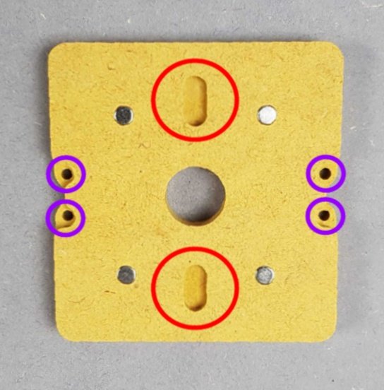
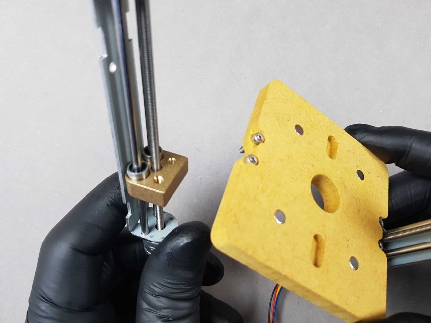
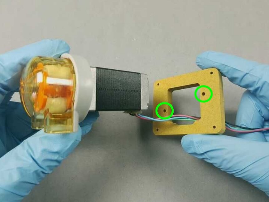
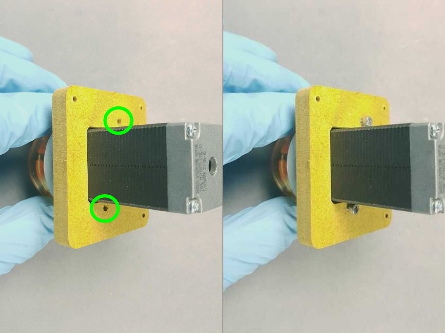
- 🔴 Lay the Part E down and make sure the pockets in these holes are facing upwards.
- 🟣 Locate the four holes on Part E and place four M2 Screws in the holes.
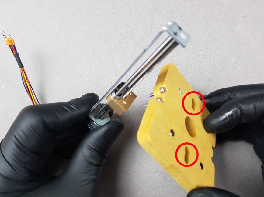
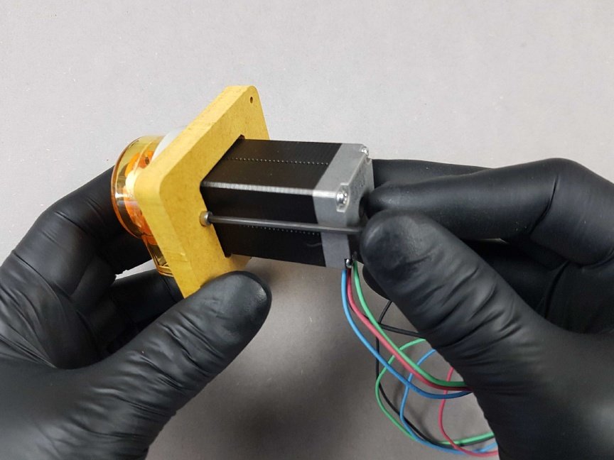
Attach the stepper motors to the screws we have just placed with the 🔴 pockets positioned on opposite to the cabling.
The result should be similar to the picture.
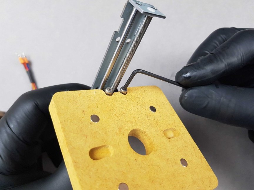
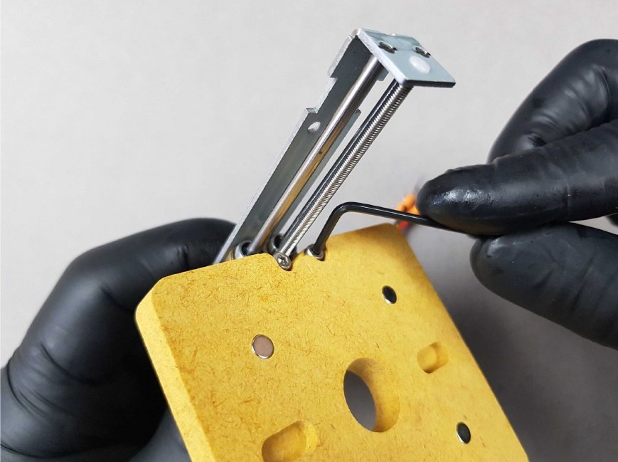
Use the 2mm allen key to fix the Stepper Motors.
The result should be similar to that picture.
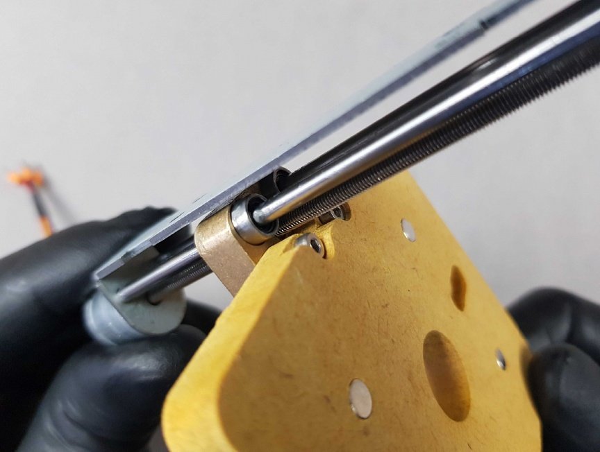
The result should be similar to the picture.
Repeat the process on the other side with the other Stepper Motor.
Repeat the process on the other side with the other Stepper Motor.
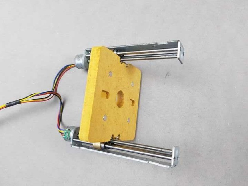
The result should be similar to the picture.
Note
🎬 Store this assembly for later.
Chapter 12: Mount the LED on Part G🔗
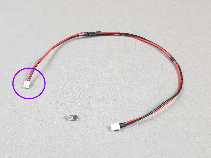
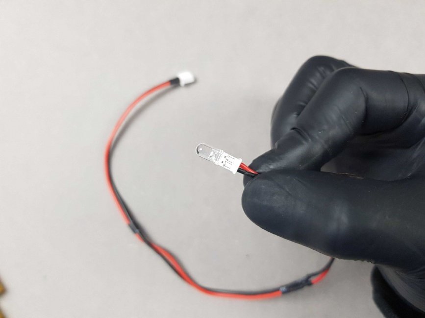
- Locate the LED and LED cable in Bag K.
- 🟣 The LED will go on the end where the white plastic connector is smallest.
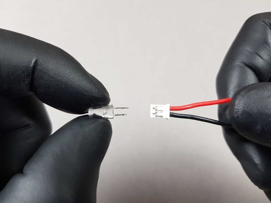
Insert the LED into the LED cable.
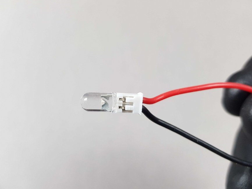
The result should be similar to the picture.
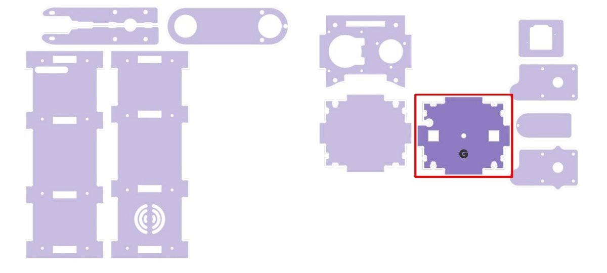
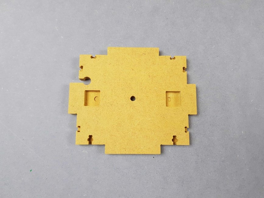
Locate part G.
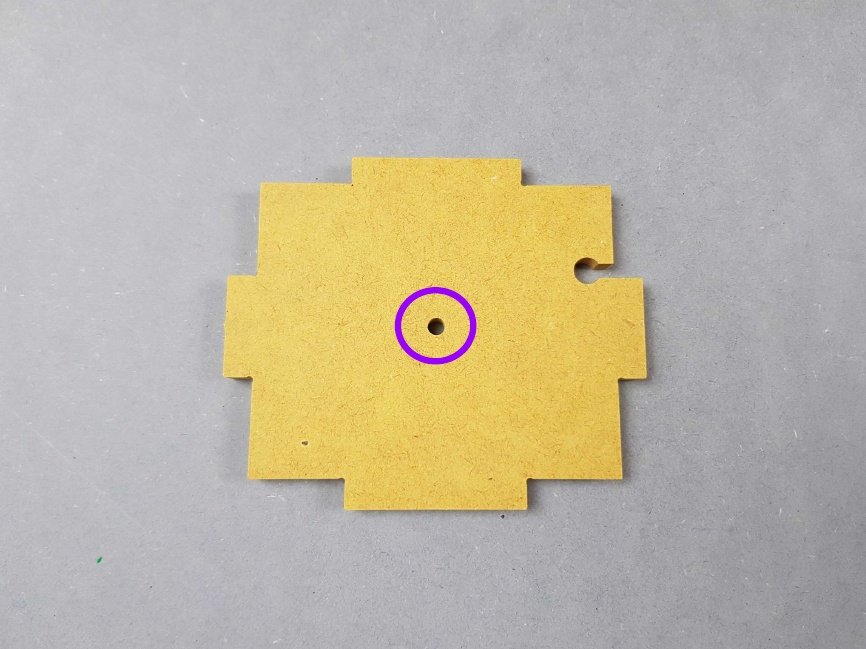
🟣 Locate the LED hole on Part G.
We will now place the LED into the slot on part G.
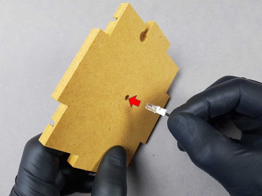
Warning
Gently push the LED into the LED hole located on Part G. It should be a snug fit.
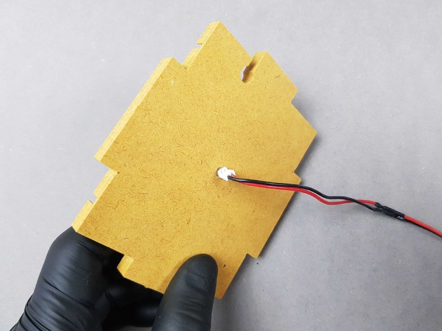
The result should be similar to the picture.
Info
🎬 Store this assembly for later.
Chapter 13: Mount the Peristaltic Pump on Part O and Part L🔗
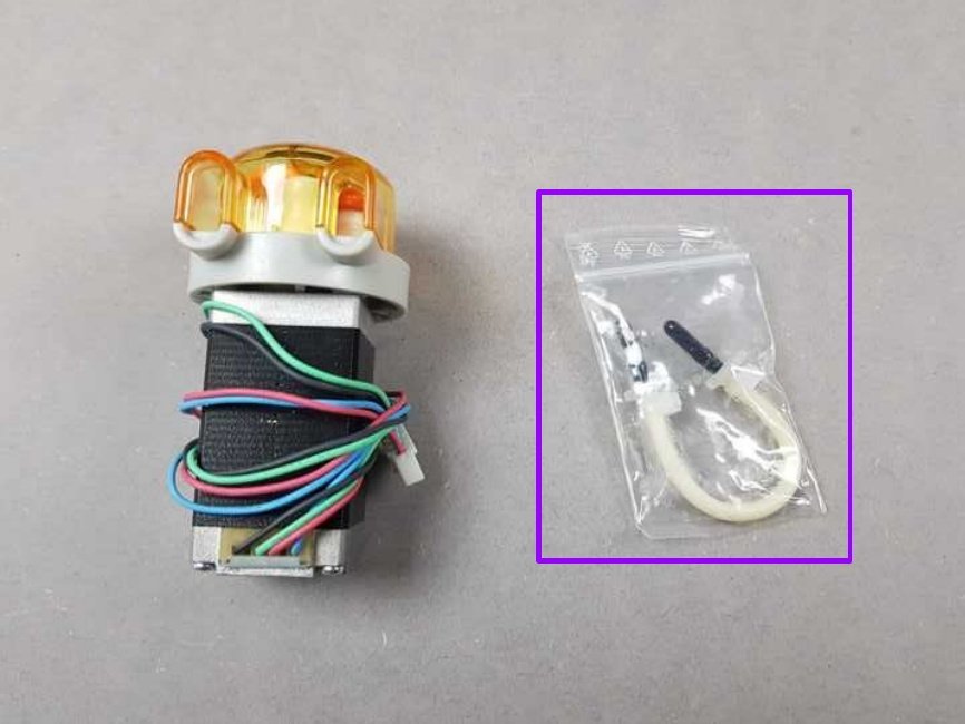
- Locate the Kamoer Peristaltic pump from the Bag F.
- 🟣 Put aside the tubing contained in the little bag.
🟢 Insert the cable of the Peristaltic Pump into the hole on Part O and then insert the motor block assembly of the pump into it.
Warning
👁 Ensure the correct orientation of Part O and the Peristaltic Pump
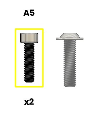
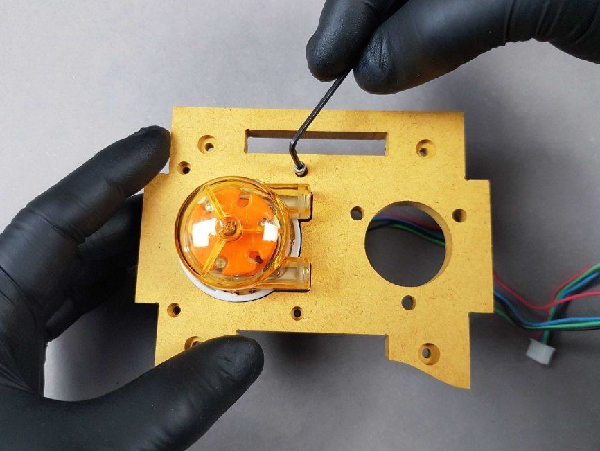
🟡 A5. Screw M2.5X10mm CHC - SS

🟡 B3. Allen key 2mm B3
🟢 Insert the two M2.5X10mm in the two holes.
Screw the two M2.5X10mm into the two holes.
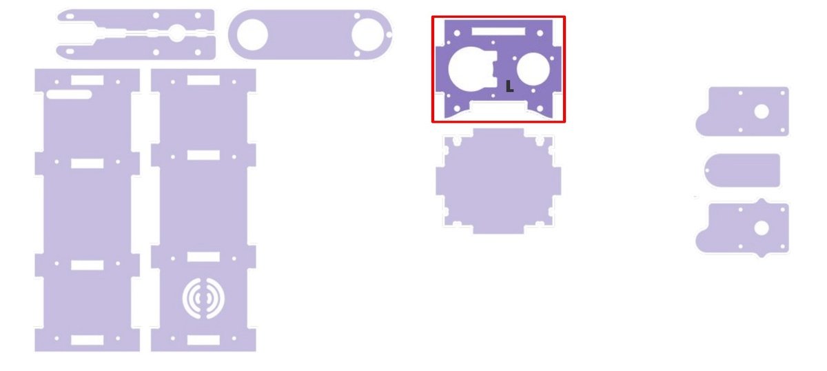
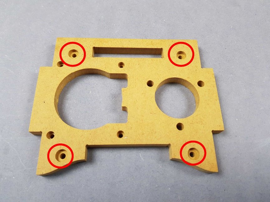
🔴 Lay the Part L down and make sure the pockets in these holes are facing upwards.
- Place the Peristaltic Pump underneath part L, ensuring the correct orientation of these two parts.
- 🔴 Insert the Peristaltic Pump into the allocated slot in Part L.
Insert the Peristaltic Pump into the allocated slot in Part L.
Insert the Peristaltic Pump into the allocated slot in Part L.
- Lay the assembly down.
- 🔴 Locate the four different holes.
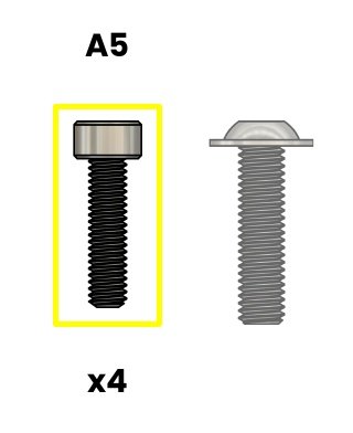
🟡 A5.Screw M2.5X10mm CHC - SS
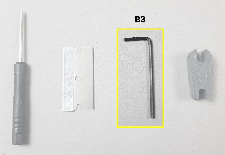
🟡 B3.Allen key 2mm
Screw the four M2.5X10mm in the located holes attaching the Part O to the Part L Peristaltic Pump.
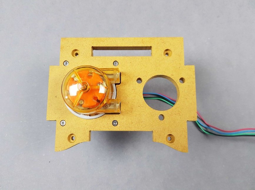 The result should be similar to the picture.
Info
We will use this part in the next step.
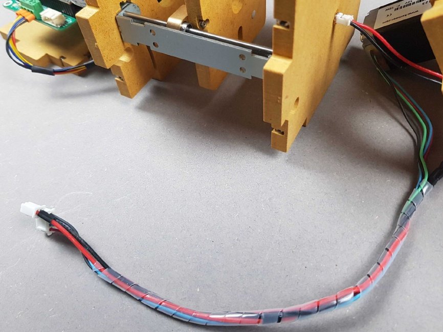
Chapter 14: Spiral wrap the LED and Peristaltic Pump cabling🔗
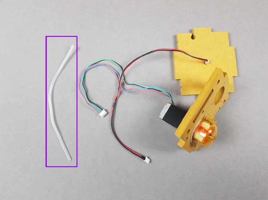
- Locate the LED and housing, along with the pump and housing.
- 🟣 Locate the spiral wrap from bag K.
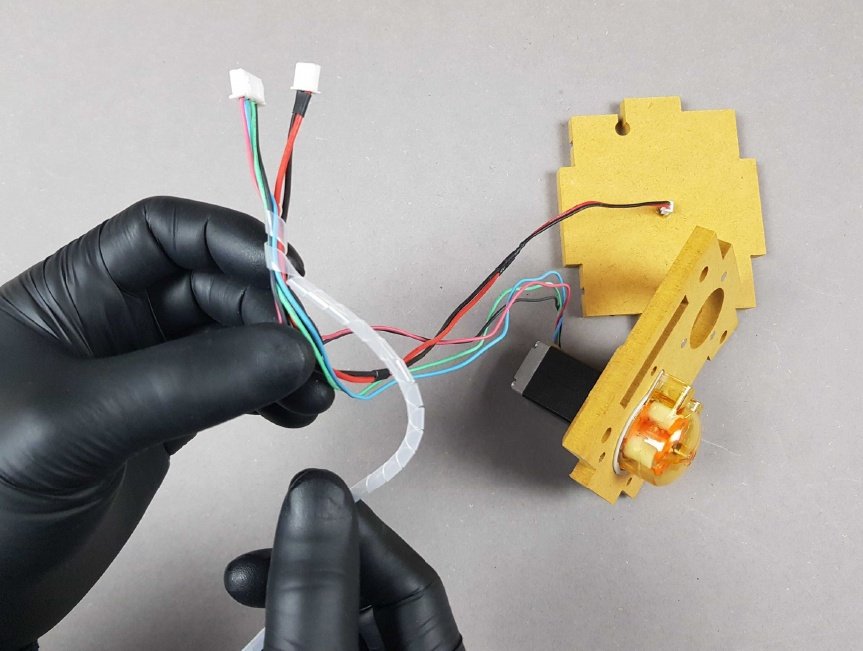
- Spiral wrap both sets of cables together.
- There should be 4 cm (1.5 inches) between the connectors and the start of the spiral wrap.
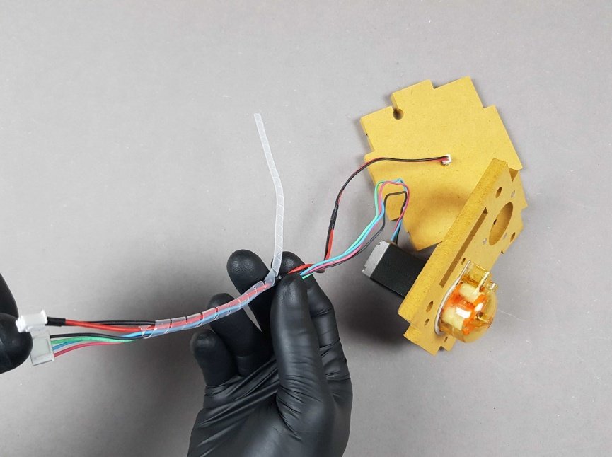
Continue wrapping around the cables until you have used all of the spiral wrap, leaving small or no gaps.
Info
The result should look the same as the picture.
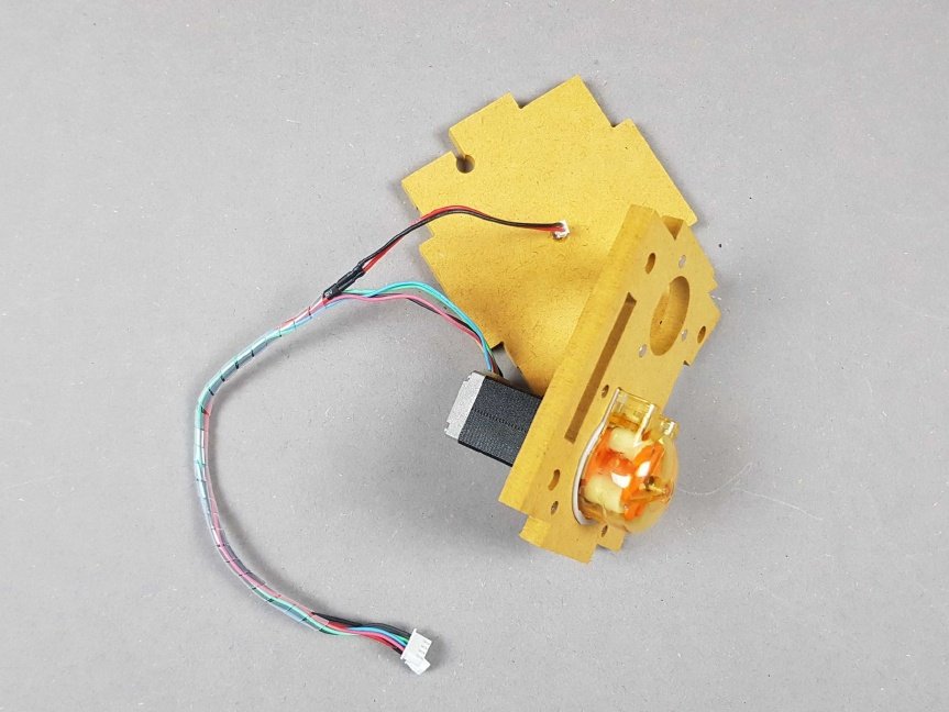
Info
The result should look the same as the picture.
Note
🎬 Store this assembly for later.
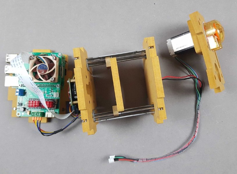
Chapter 15: Attaching the Stepper Motors to the Raspberry Pi Camera🔗
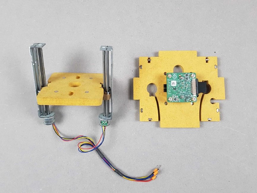
Locate the Stepper Motors with mount, and the Raspberry Pi Camera.
 Feed the Stepper Motor cables into the slots either side of the Raspberry Pi Camera.
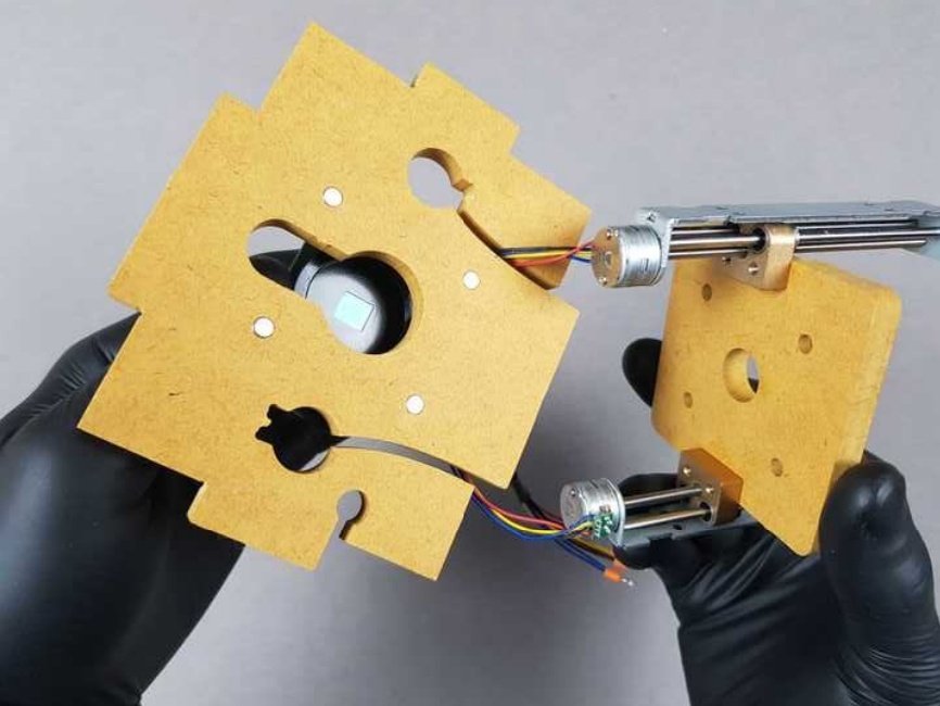
Warning
Make sure the orientation is correct and matches the picture.
 Feed the Stepper Motor cables into the slots either side of the Raspberry Pi Camera.
Warning
Make sure the orientation is correct and matches the picture.
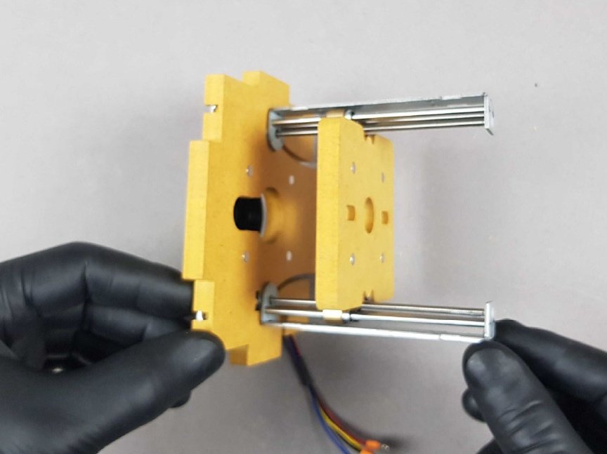
Then insert the cylindrical parts of the Stepper Motor into the slots.
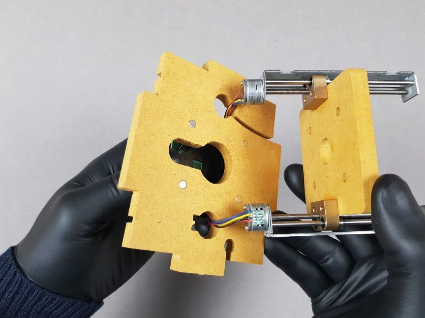
Feed the Stepper Motor cables into the slots either side of the Raspberry Pi Camera.
Warning
Make sure the orientation is correct and matches the picture.
Then insert the cylindrical parts of the Stepper Motor into the slots.
Note
The result should be the same as the picture.
Chapter 16: Connecting the Raspberry Pi Camera to the Raspberry Pi HAT🔗
- We will need the Raspberry Pi HAT with housing and Ribbon Cable along \ with the Raspberry Pi Camera with Stepper Motors and housing.
- We will be connecting the 🟢Ribbon Cableto the 🟡black Raspberry Pi Camera connector that we removed it from earlier.
Gently feed the Ribbon Cable into the port of the Camera.
Warning
👁 Ensure the correct orientation of the Ribbon Cable with the blue end facing upwards.
 🔴 Press down on the black connector on the Raspberry Pi camera board once the Ribbon Cable is in position.
 🔴 B1.Small flat screwdriver 2mm
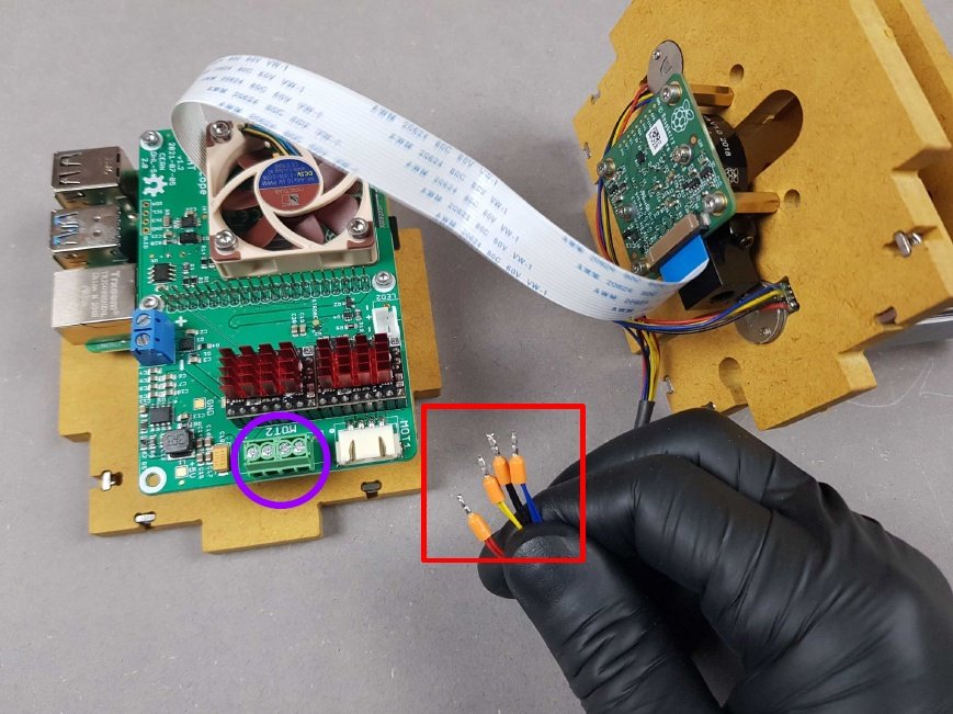
- Now we will plug in the Stepper Mounts to the HAT.
- 🔴The cables for the Stepper Mounts will be plugged into the HAT 🟣here.
Warning
Hold tight, a specific order is required.
Starting with the red cable, insert the cable in the far left port and tighten the screw situated above the port.
Note
The result should look the same as the picture.
Repeat this process with the order pictured here from left to right: 🔴 Red 🟡 Yellow 🔵 Blue ⚫ Black.
Chapter 17: Connect the LED and Peristaltic Pump to the Raspberry Pi🔗
We will now be connecting the LED and Peristaltic Pump with the Raspberry Pi HAT and Camera.
Place the LED housing onto the Stepper Mounts.
Warning
👁 Ensure correct orientation of both 🟣 parts by looking at the precut holes.
Info
The result should be similar to the picture.
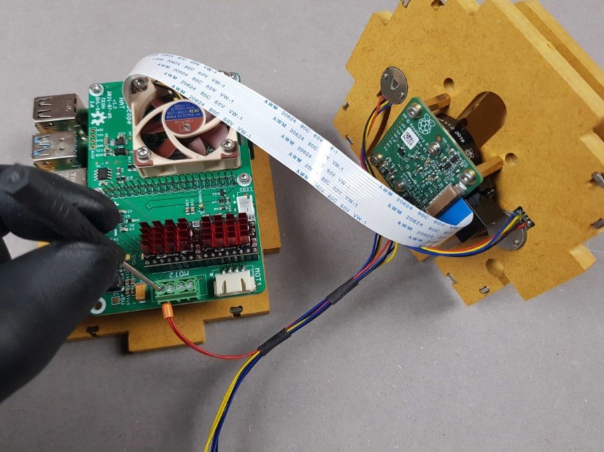
Now we will plug in the LED and Stepper Mount cables to the Raspberry Pi.
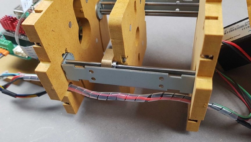
Feed the area of cabling that is not covered by the spiral wrap through the two holes to start. Then thread through to the spiral wrap so that it matches the picture.
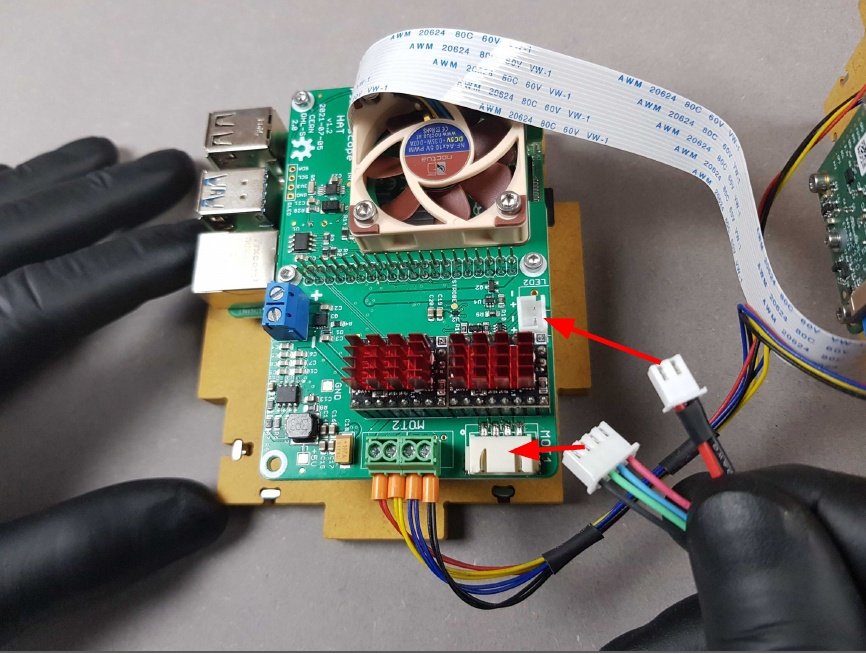
We will now plug the cables into the correct ports.
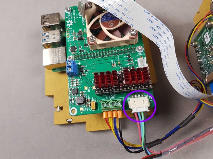
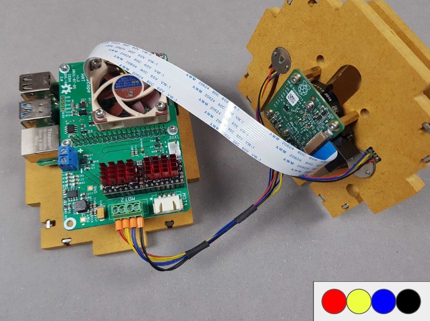
🟣 The four wires (🔴 Red 🔵 Blue 🟢 Green ⚫ Black) enter the side port on the Raspberry Pi HAT.
🔴 The two wires (LED) enter on the port on top of the Raspberry Pi HAT.
The result should be similar to the picture.
Note
We will use this assembly in the next step.
Chapter 18: Connect the DC Power Jack to the Raspberry Pi🔗
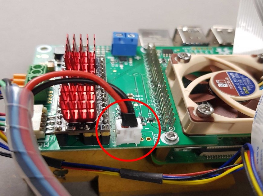
- 🟢 Locate the DC Power Jack
- We will plug the DC Power Jack into the Raspberry Pi via the 🔵 blue port.
🔴 B1.Small flat screwdriver 2mm
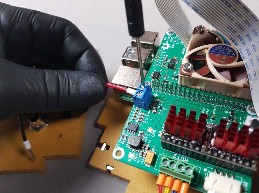
- Insert the 🔴 red cable of the DC Power Jack into the left side of the blue port.
- Tighten the screw above.
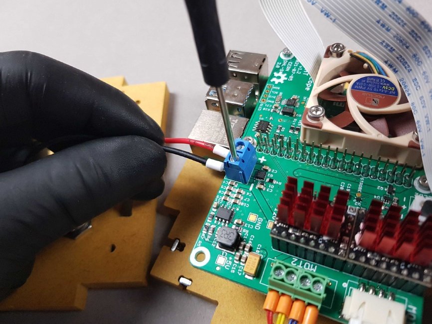
- Insert the ⚫ black cable of the DC Power Jack into the right side of the blue port.
- Tighten the screw above.
Info
The result should be similar to the picture.
Note
We will use this assembly in the next step.
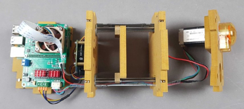
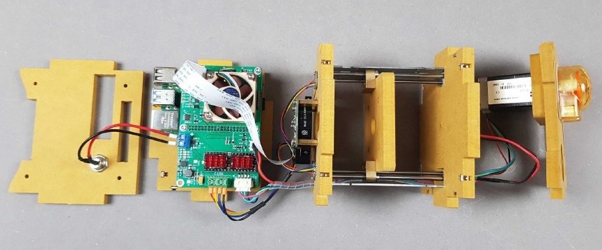
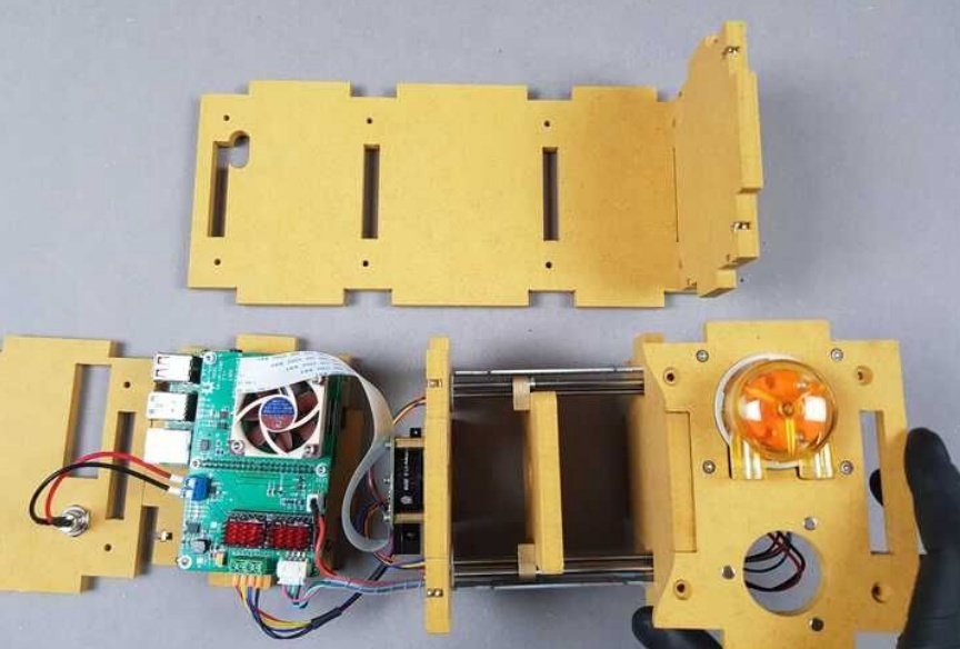
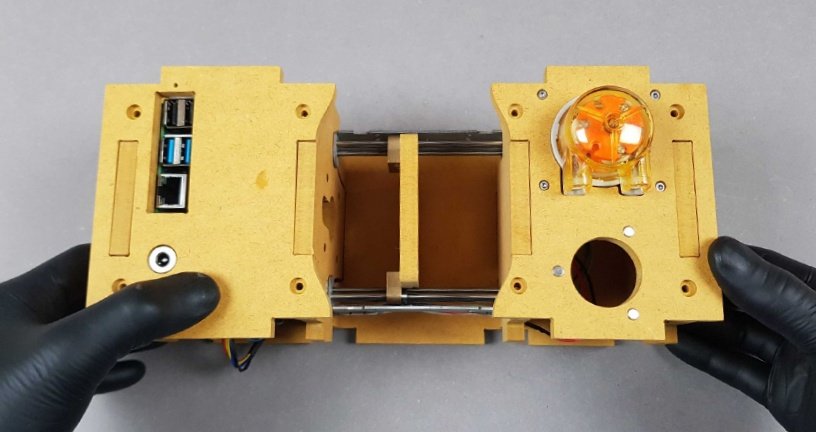
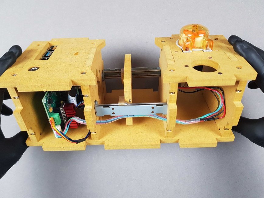
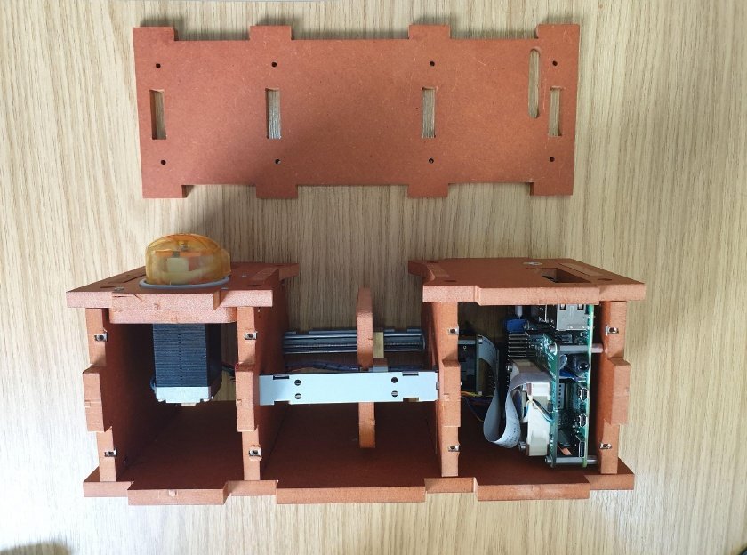
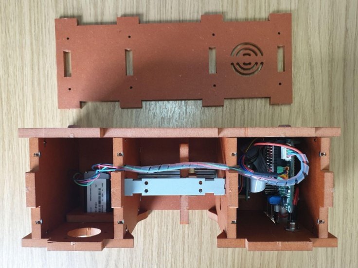
Chapter 19: Your PlanktoScope starts to take shape🔗
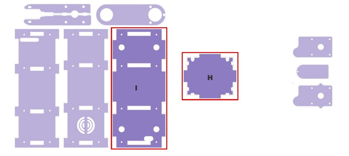
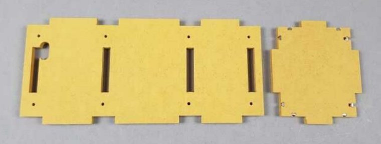
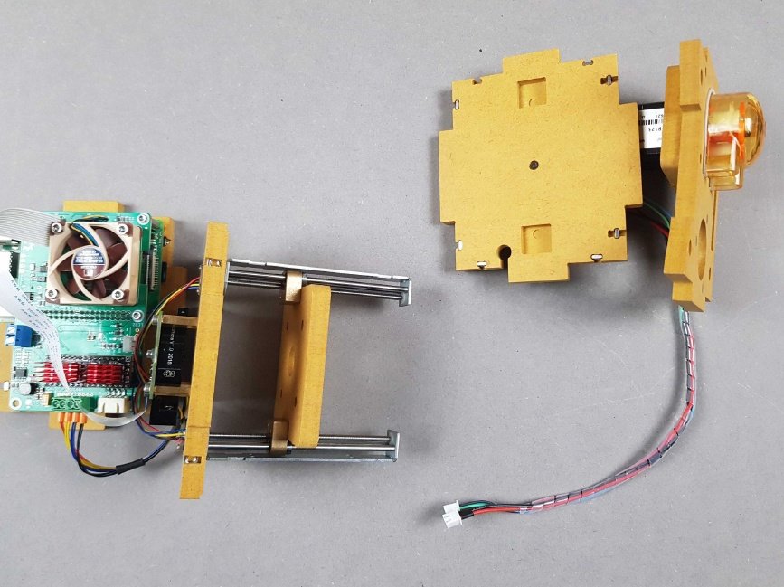
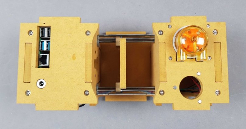
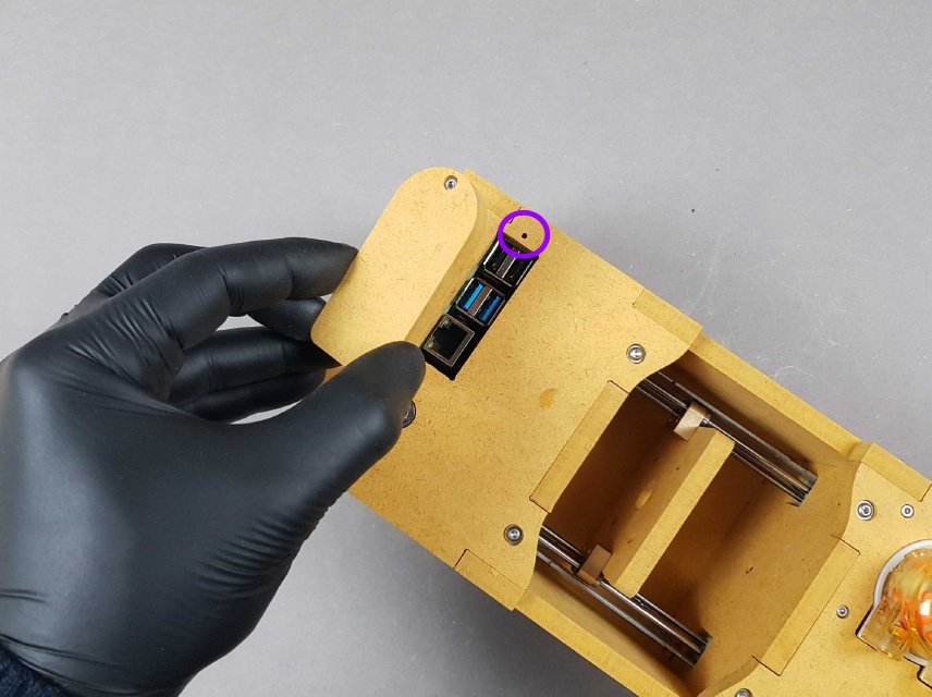
Locate Part I and Part H.
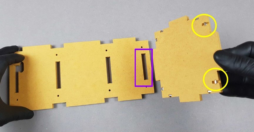
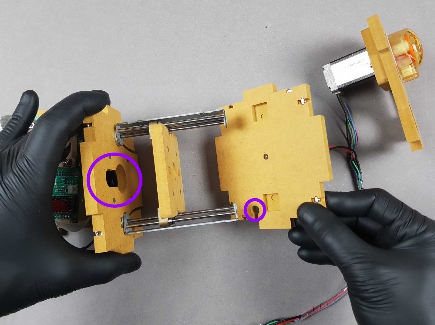
- Slot Part H into Part I.
- 🟣 Note the orientation. Part H goes into Part Iat the end with the rectangular slot (as opposed to the rectangle with bulbous hole).
- 🟡 Also, the deeper slots on part H should be on the upper side.
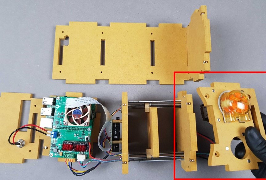
🔴 Slot the Peristaltic Pump above the LED.
Note
The result should be the same as the picture.
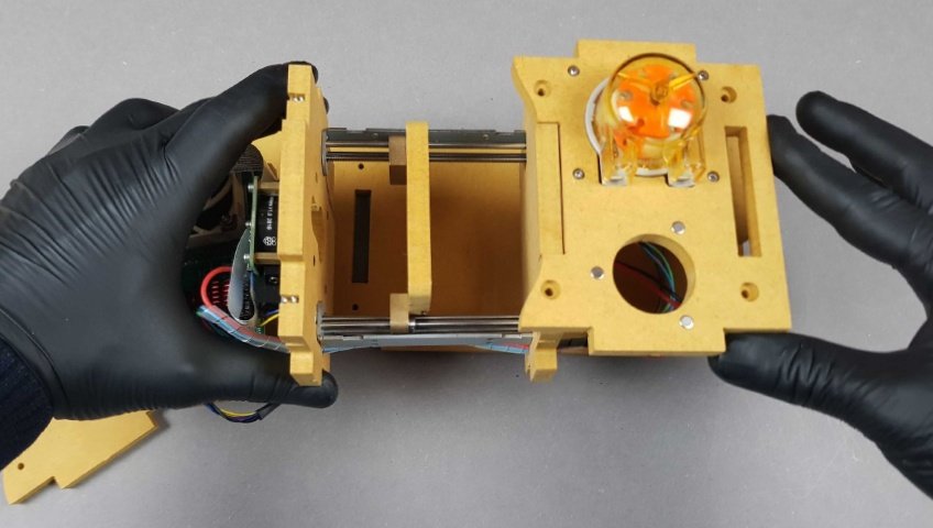
Warning
👁 Ensure the correct orientation of the housing and the Peristaltic Pump.
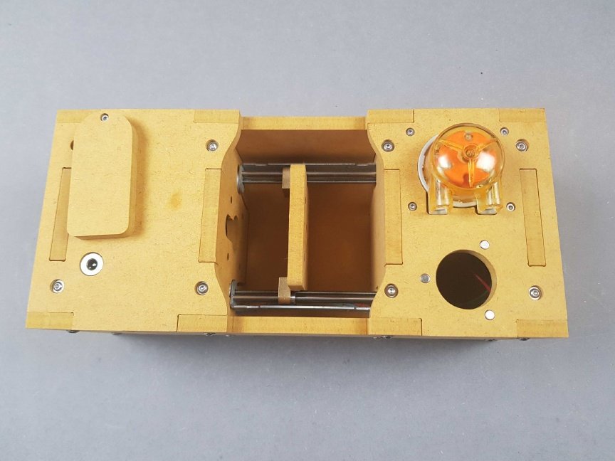
At the other end, slot the DC Power Jack housing adjacent to the Raspberry Pi.
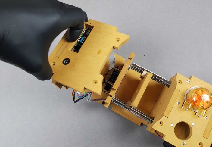
Rotate so that the DC Power Jack is facing upwards. We will now slot the Raspberry Pi onto the rest of the housing.
Info
The result should be similar to that picture.
Note
🎬 Store this assembly for later.
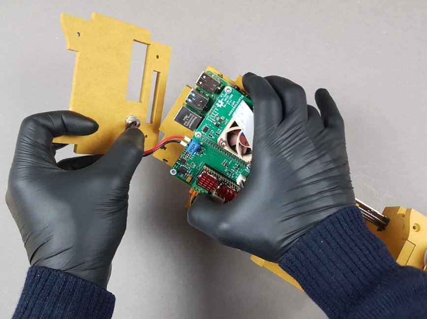
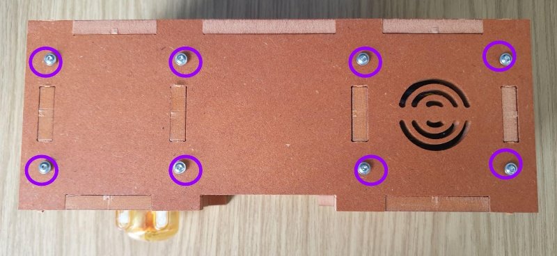
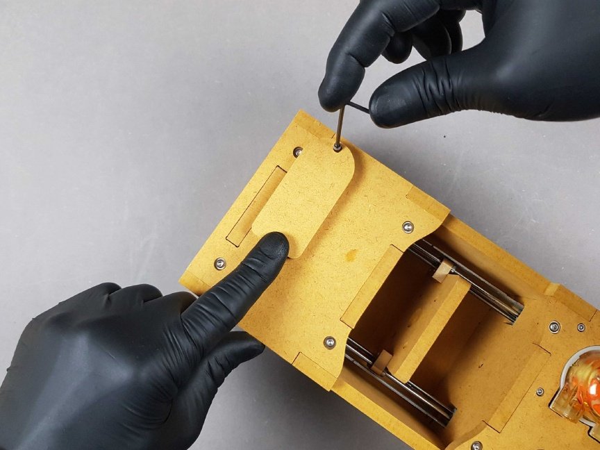
Chapter 20: Inserting screws🔗
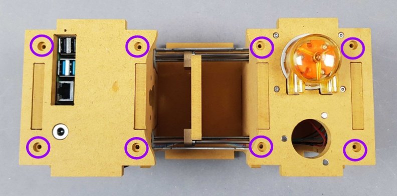
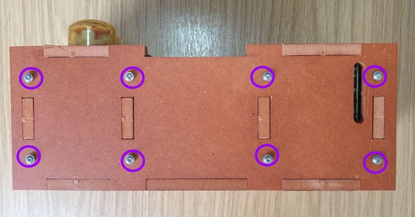
🟣 We will now insert eight M3 screws to fasten the housing together.
Note
🎬 Store this assembly for later.
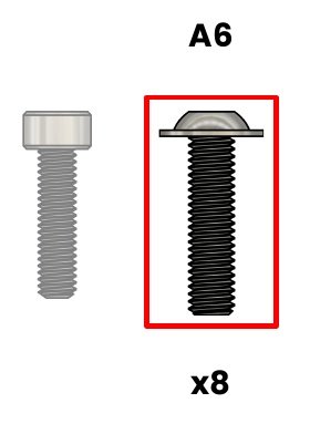
🔴 A6. Screw M3X12mm BHC - SS
🟡 B3. Allen key 2mm
Info
The result should be similar to the picture.
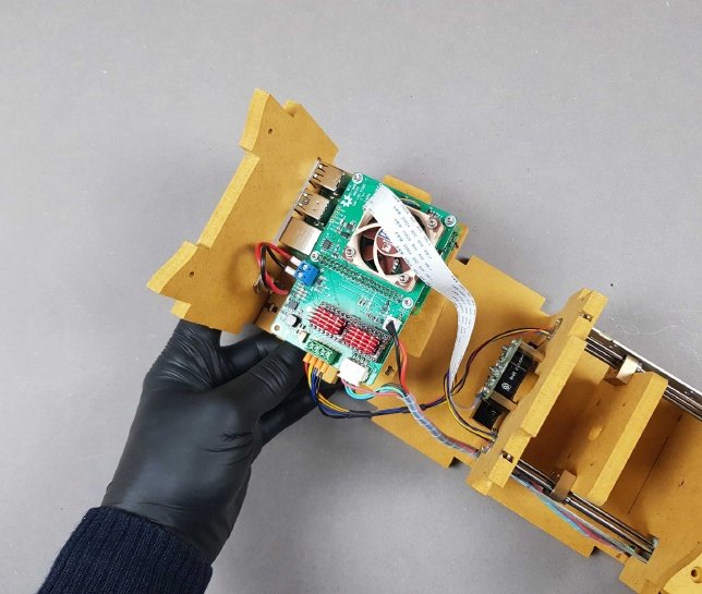
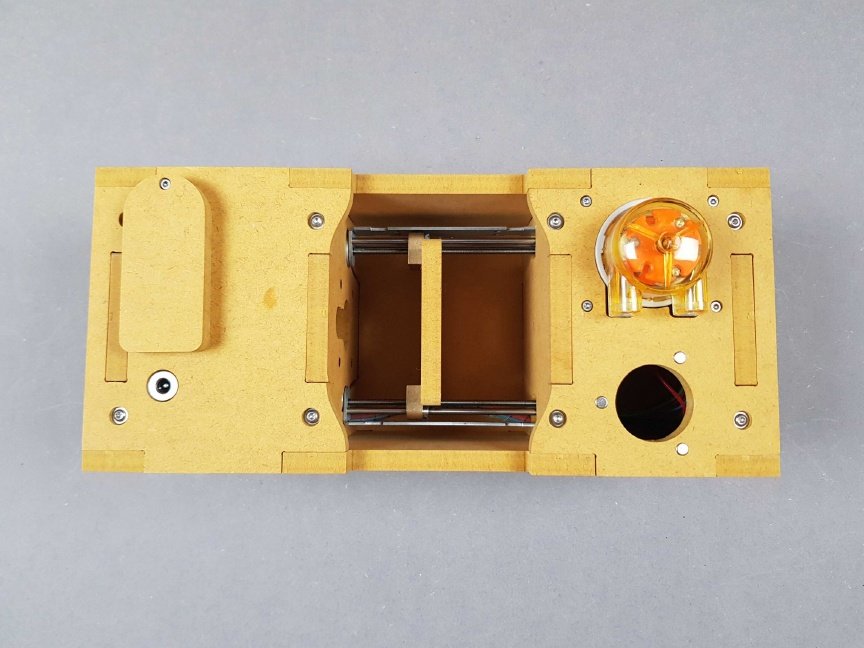
We will now turn over the PlanktoScope and repeat the process for the underside.
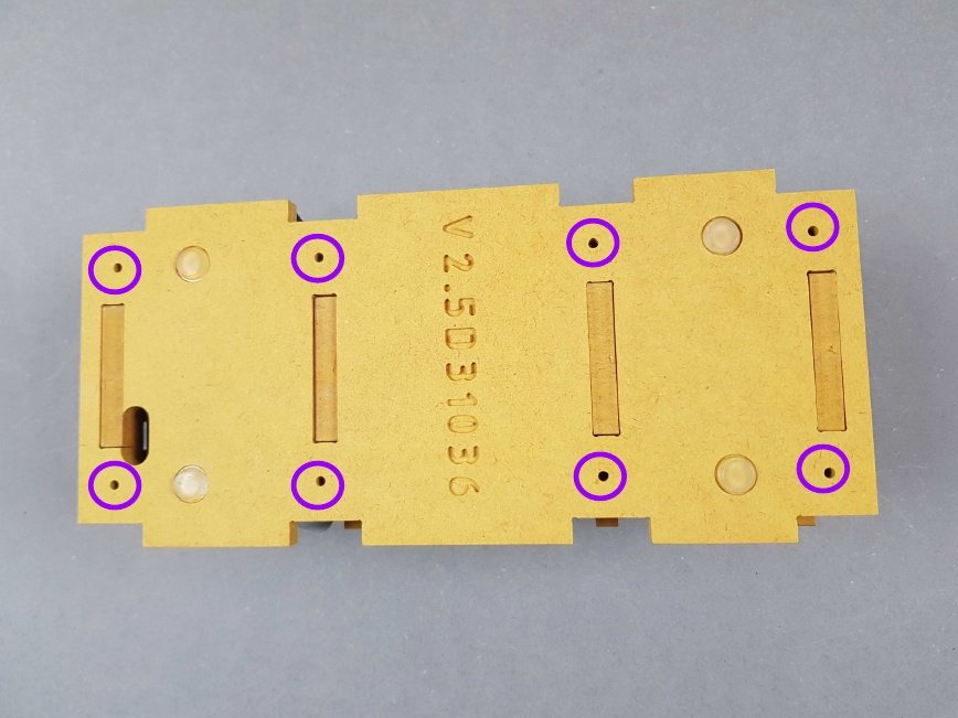
🟣 Insert eight more M3 screws on the underside.
Info
The result should be similar to the picture.
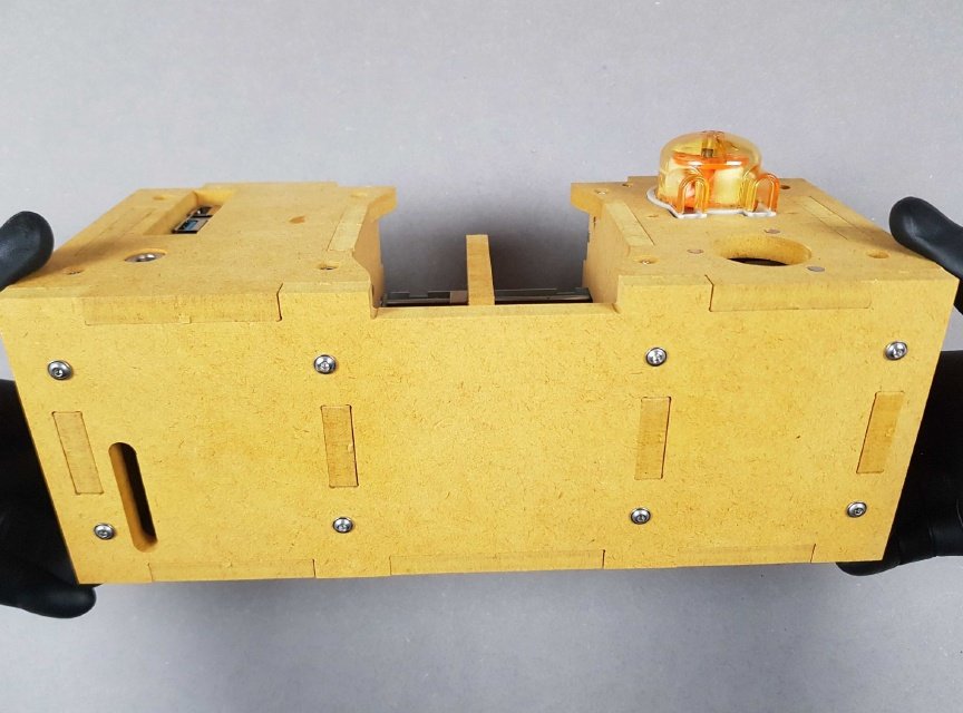
Now turn the PlanktoScope on its side.
Warning
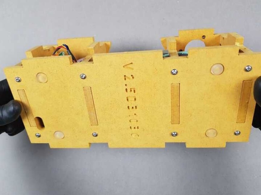
👁 Ensure the orientation of your PlanktoScope and Part K matches the picture.
Slot Part K onto the rest of the PlanktoScope.
Warning
🟢 Ensure the correct orientation. The result should look the same at the picture.
Content of Bag A: 🔴 A6. Screw M3X12mm BHC - SS

Content of Bag B: 🟡 B3. Allen key 2mm
🟣 Insert eight more M3 screws on the side to hold Part K in place.
We will now place Part J into position as the housing for the side.
Warning
👁 Ensure your PlanktoScope matches the orientation in the picture.
🟢 Place Part K onto the rest of the PlanktoScope and note the position of the cutout.
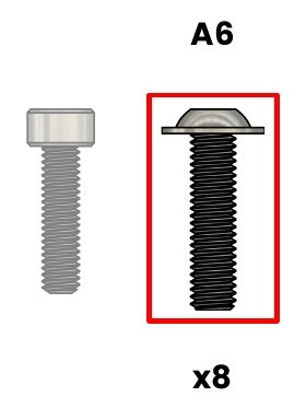
Content of Bag A: 🔴 A6. Screw M3X12mm BHC - SS

Content of Bag B: 🟡 B3. Allen key 2mm
🟣 Insert eight more M3 screws on the underside
Info
The result should be similar to the picture.
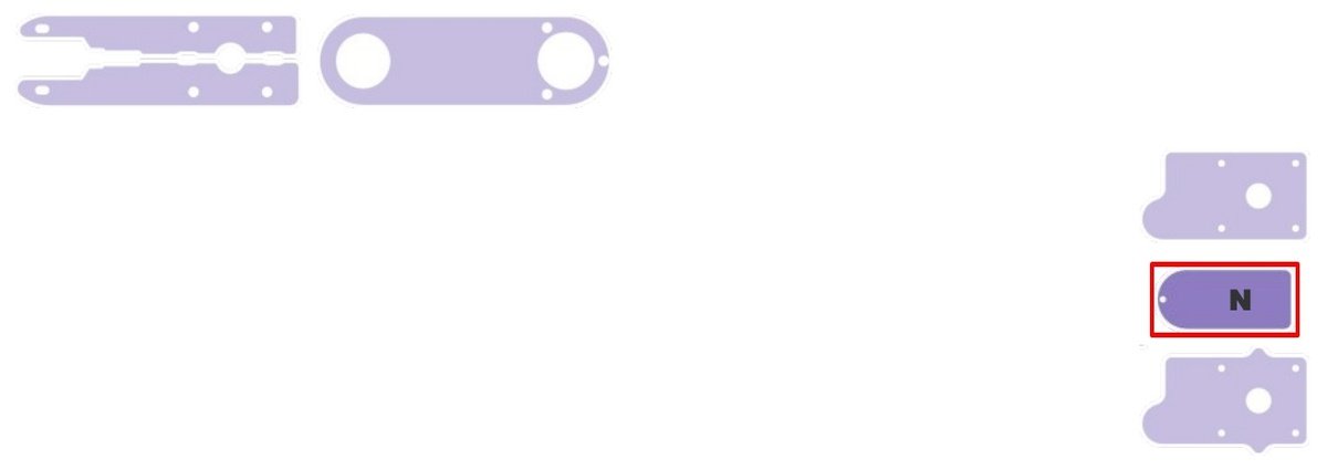
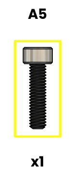
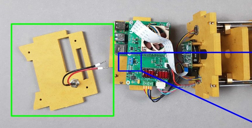
Content of Bag A: 🟡 A5. Screw M2.5X10mm CHC - SS
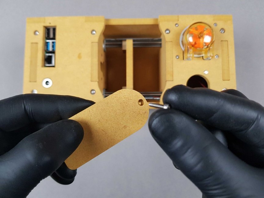
Place the M2.5 screw through Part N. It will act as a cover for the electrical inputs.
- Place the cover over the electrical inputs on the PlanktoScope.
- 🟣 The screw will enter the hole located here.
Using the allen key, tighten the screw so that it is possible to move the cover with light force.
Info
The result should be the same as the picture.
Chapter 21: Insert the tubing in the Peristaltic Pump🔗
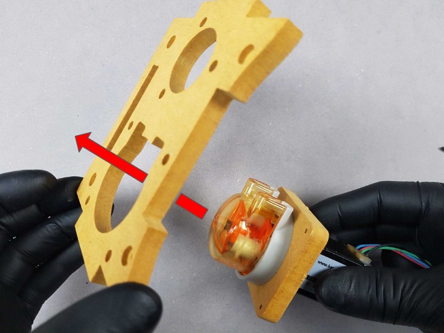
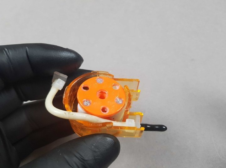
- Orientate your PlanktoScope so that it matches the picture.
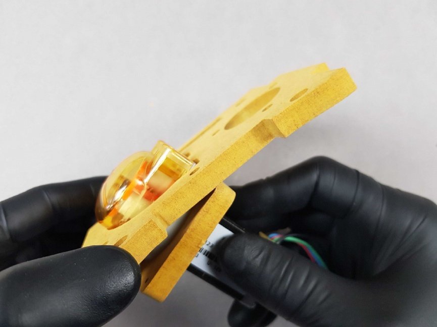
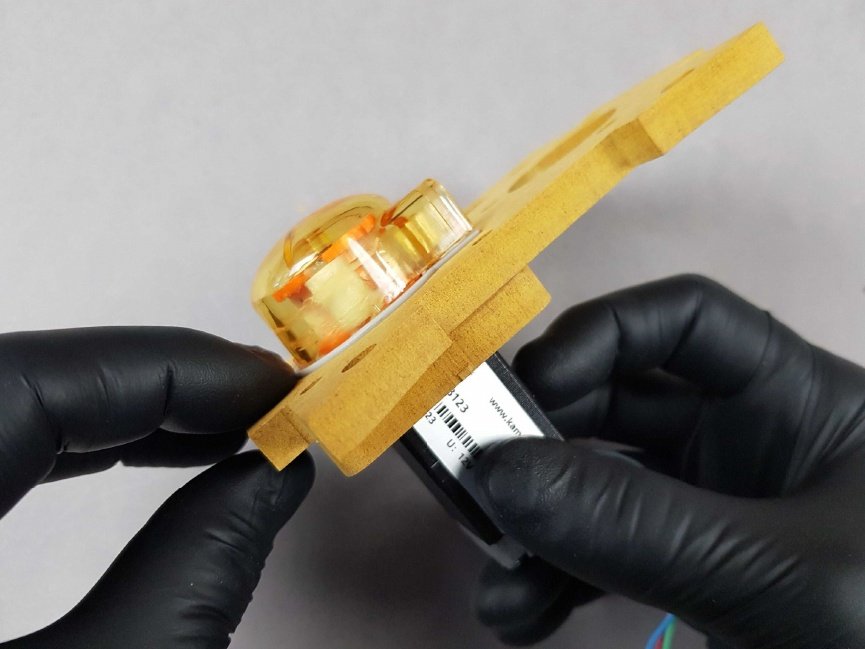
- Twist off the orange top of the Peristaltic pump in an anti-clockwise direction.
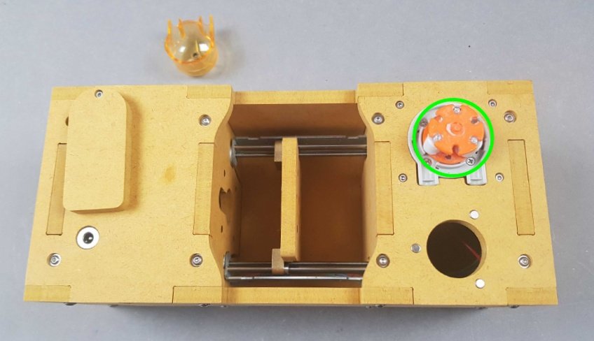
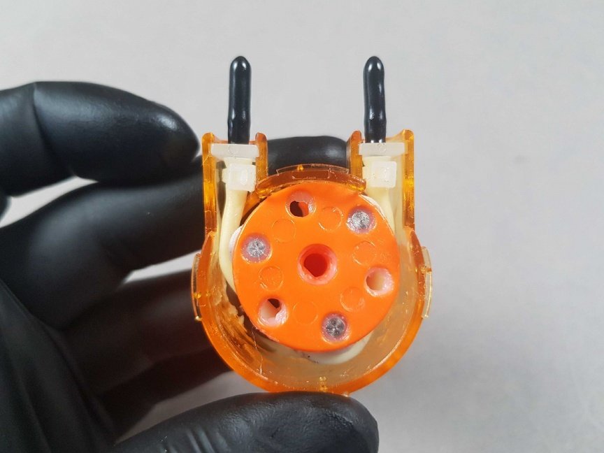
You can now remove the Peristaltic Pump housing and 🟢 Rotor.
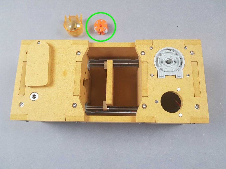
You can now remove the Peristaltic Pump housing and 🟢 Rotor.
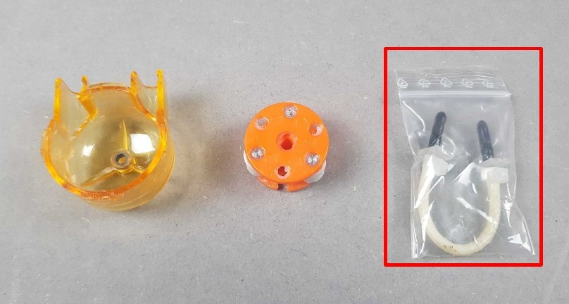
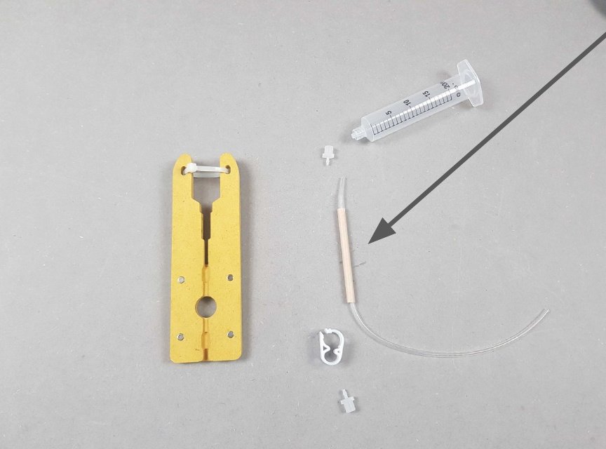
🔴 Locate the Tube for the Peristaltic Pump in Bag F and remove it from the bag.
Warning
The tips of the Tubing that are covered by black rubber are very delicate and easily broken.
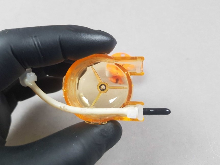
Insert the first plastic arch of the Tube into the slot on the Peristaltic Pump \ housing.
Info
The result should be similar to the picture.
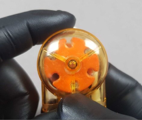
Insert the Rotor into the housing ensuring the correct orientation. The hole in the centre should be visible on the underside.
Info
The result should be similar to the picture.
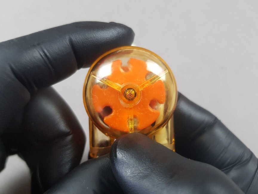
Insert the Rotor into the housing. Then, thread the Tube around the Rotor and insert the other plastic arch into the second slot.
Info
The result should be similar to the picture.
- Thread the Tube around around the Rotor and insert the other plastic arch into the second slot.
- This will require stretching the Tube slightly.
Info
The result should be similar to the picture.
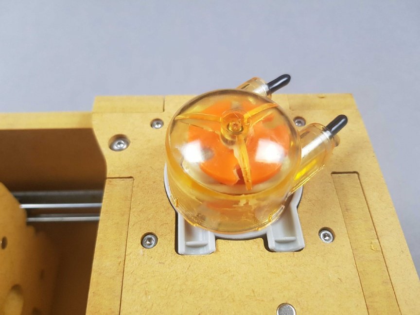
Place the Peristaltic Pump housing back onto the PlanktoScope.
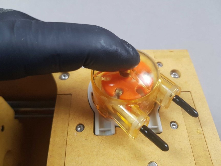
Achieve the angle shown in the picture between the Peristaltic Pump housing and PlanktoScope main body. Then, press and twist in a clockwise direction.
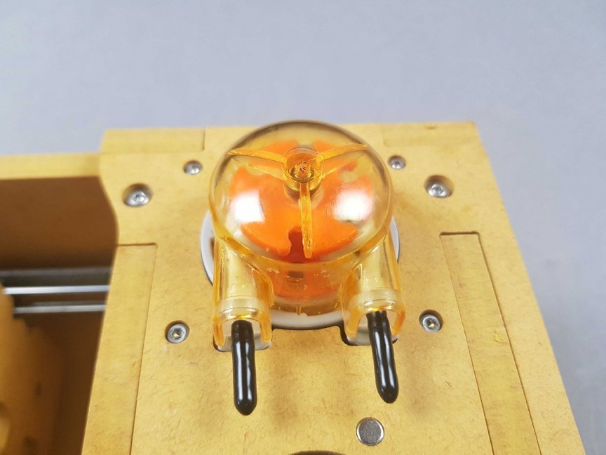
Info
The result should be similar to the picture.
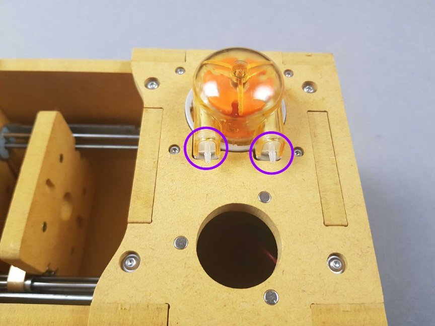
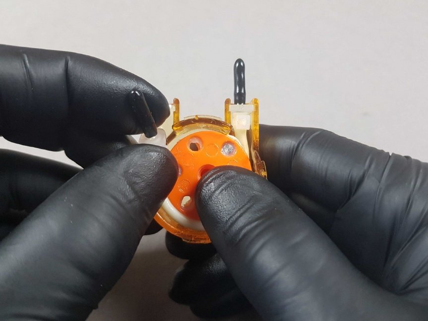
- 🟣 Gently remove the black rubber covers for the Peristaltic Pump connectors by pinching the very tip and pulling away.
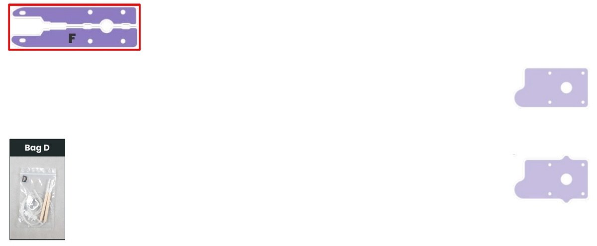
- Once complete, locate Bag D which contains tubing.
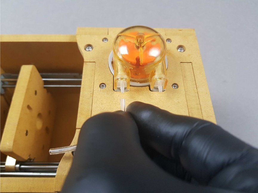
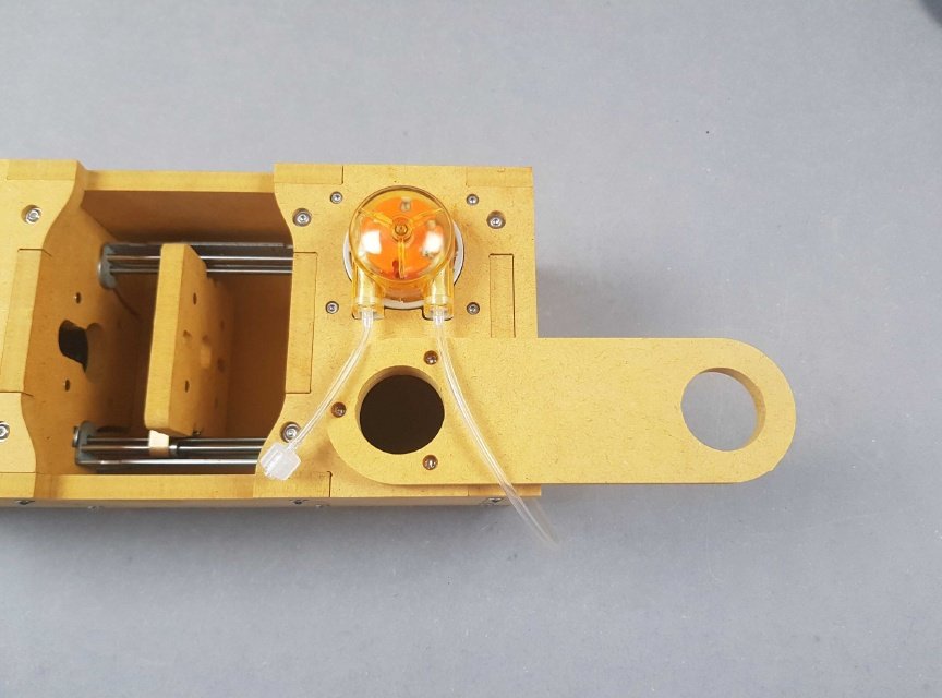
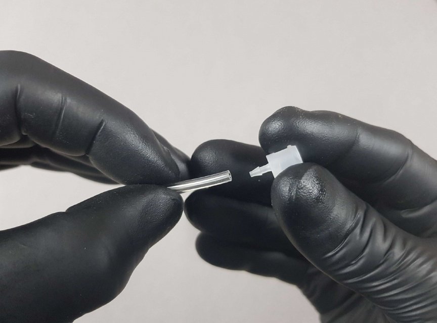
Push the small piece of tubing from Bag D over the left-side connector of the Peristaltic Pump.
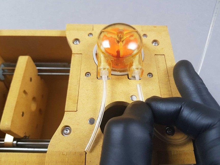
Place the long piece of tubing from Bag D over the right-side connector of the Peristaltic Pump.
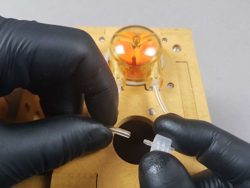
Insert the connector from Bag D into the other end of the small piece of tubing.
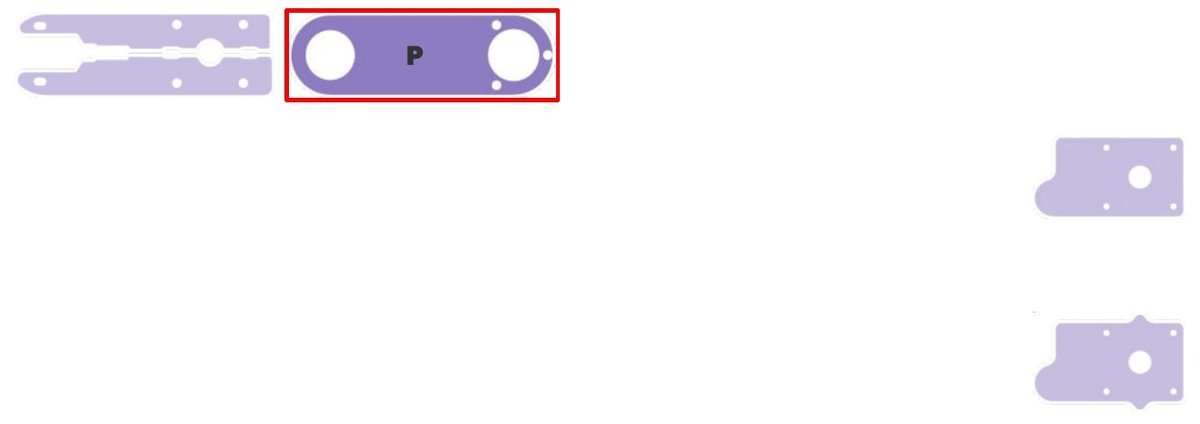
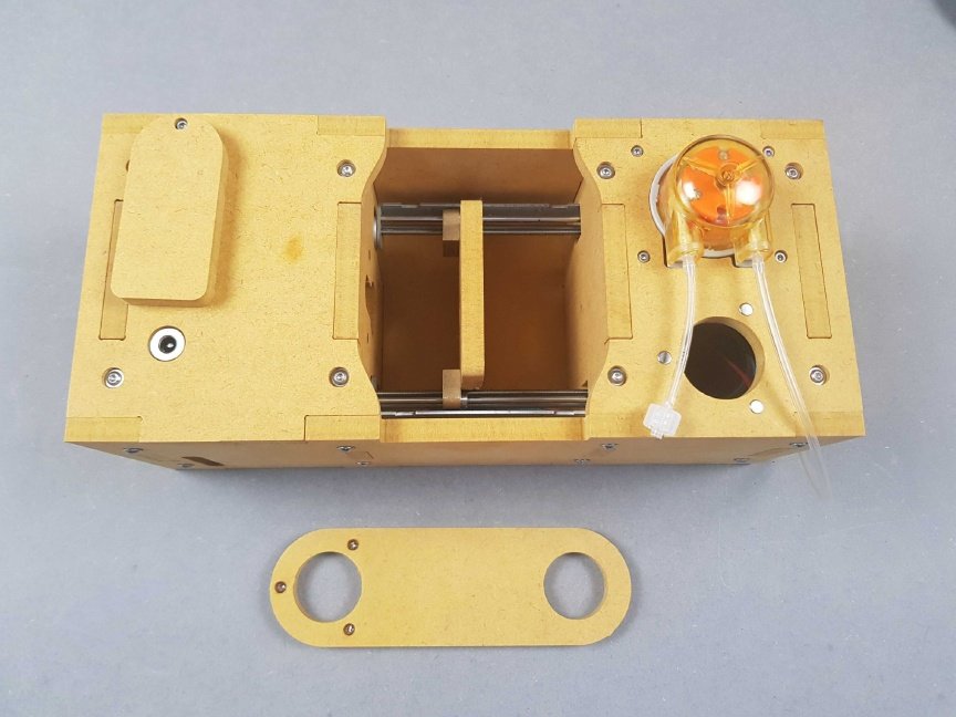
Orientate Part P so that the magnets are face-down on the left-hand side.
Place Part P over the magnets adjacent to the Peristaltic Pump.
Info
The result should be similar to the picture.
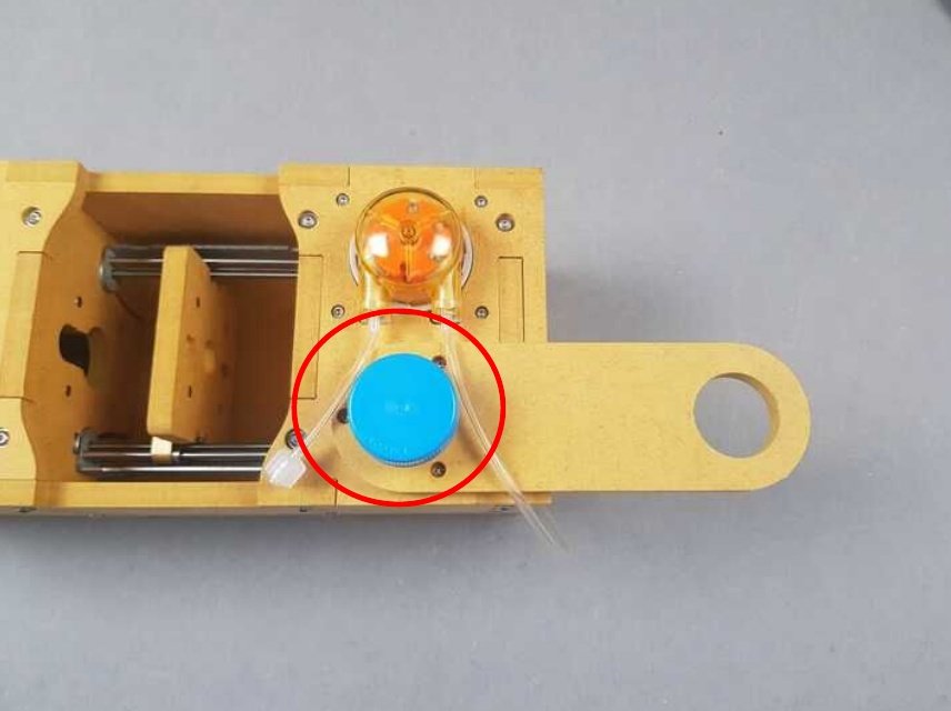
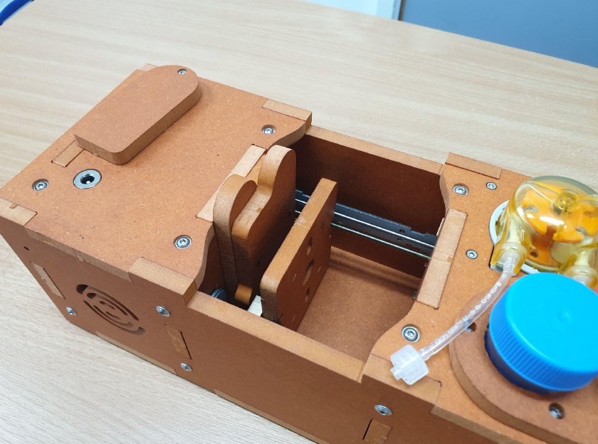
🔴 From Bag M, Place the light blue Test Tube in the hole adjacent to the Peristaltic Pump.
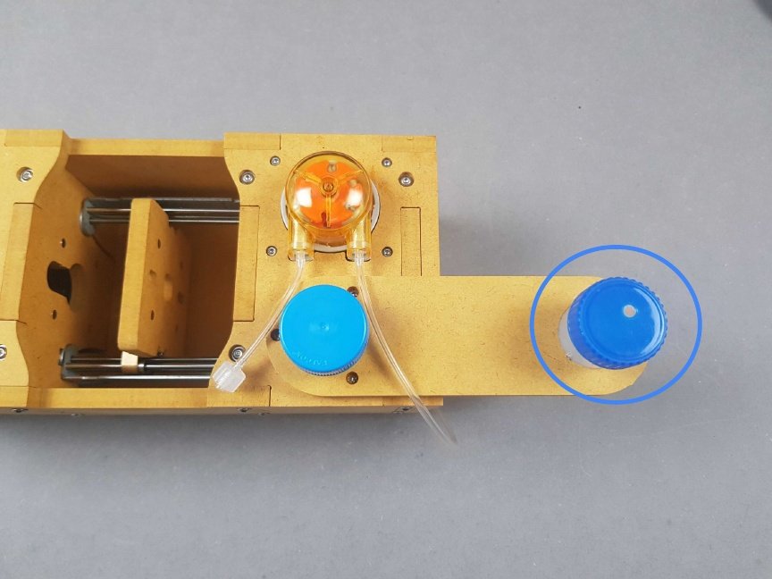
Place the 🔵 dark blue Test Tube into the hole situated outside of the PlanktoScope.
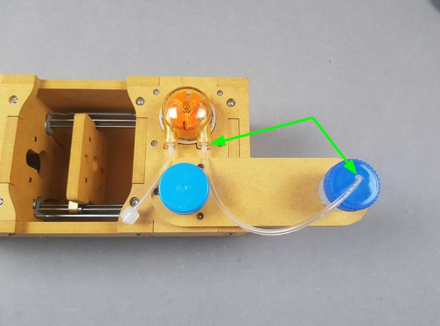
🟢 Insert the other end of the long piece of tubing into the 🔵 dark blue Test Tube. This will serve as the waste container. The result should look the same as the picture.
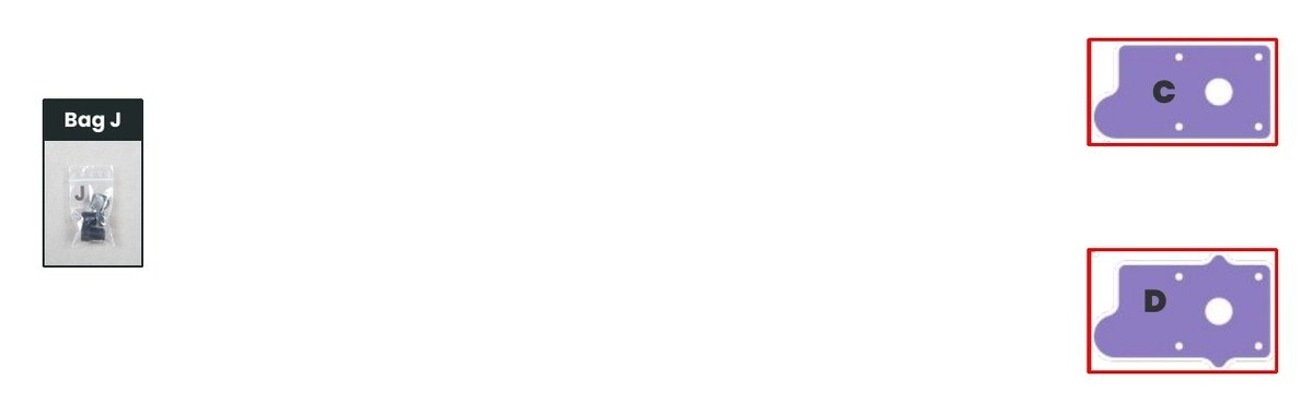
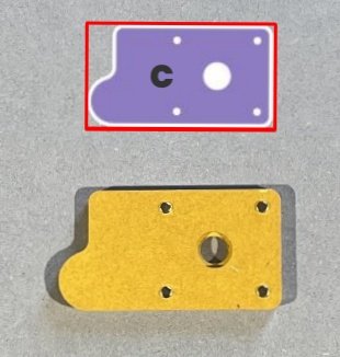
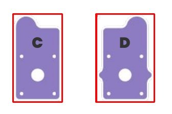
- Locate Part C
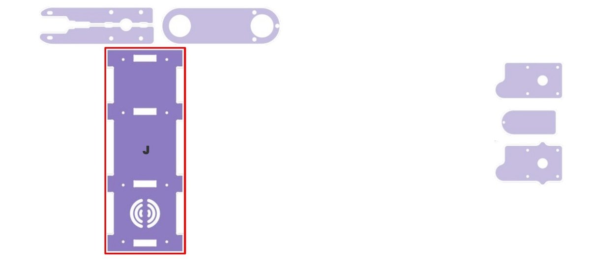
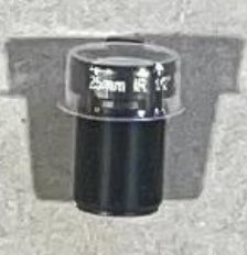
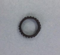
- Locate 25 mm camera lens and Lock Ring from Bag J.
- 25MM is printed on the lens.
- Remove the plastic lens cap.
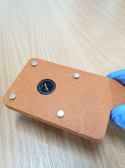
- Slot the 25 mm camera lens into Part C.
Info
The magnets are raised on the side where the lens lays flat.
Warning
Try not to touch the lens
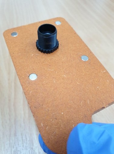
Screw the Lock Ring onto the lens, flat-side down.
- Locate Part D.
- Locate 16 mm camera lens and Lock Ring from Bag J.
- 16MM is printed on the lens.
- Remove the plastic lens cap.
- Slot the 16 mm camera lens into Part D.
Info
The magnets are indented on the side that the lens lays flat.
Warning
Try not to touch the lens
Screw the Lock Ring onto the lens, flat-side down.
The result should be similar to that picture.
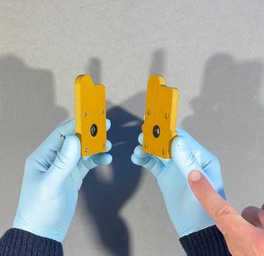
Place both Lenses (C and D) together so that they flat together and both lenses are facing each other.
Info
The result should be similar to the picture.
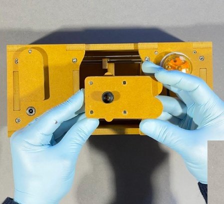
Place the Lenses (both C and D) into position, adjacent to the camera.
The orientation of your PlanktoScope and Lenses should match the pictures.
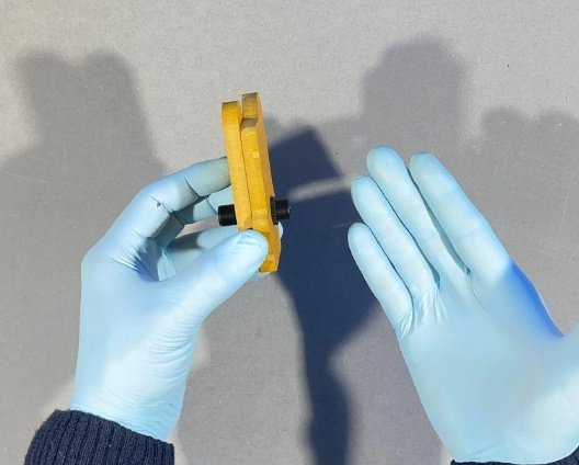
- Once together, place the lenses (both C and D) into position, adjacent to the camera.
- Part C / 25mm lens should be furthest from the pump (orange piece).
Info
The result should be similar to the picture.
Info
The Fluidic Path will have a cardboard protector.
Please take extra precaution while handling this part and avoid touching the glass element of the piece.
Warning
The Fluidic Path is very delicate.
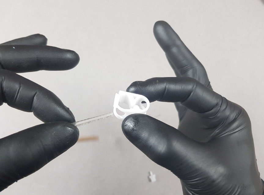
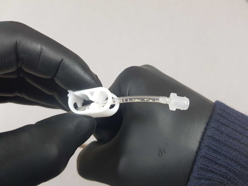
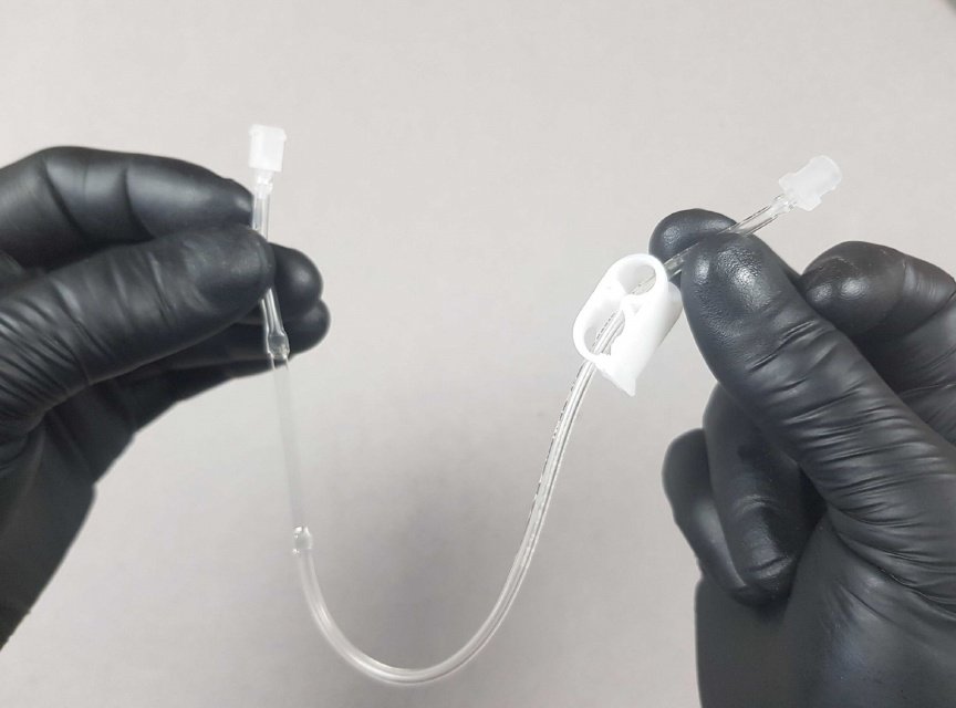
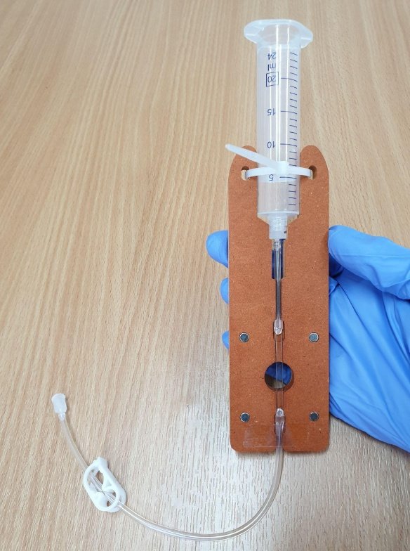
Place the Tube Clamp over the long piece of tube at the end of the Fluidic Path.
Place the white clamp over the long piece of tube at the end of the Fluidic Path.
Info
The result should look the same as the picture.
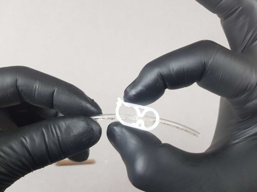
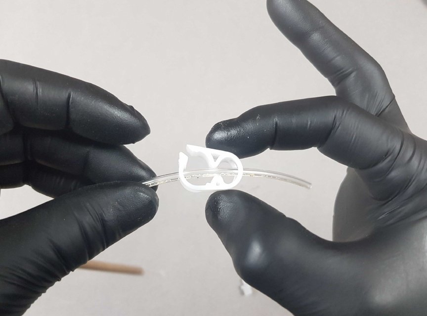
Press down on the Tube Clamp so that it clicks into place with just one click.
Info
The result should look the same as the picture.
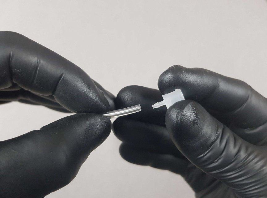
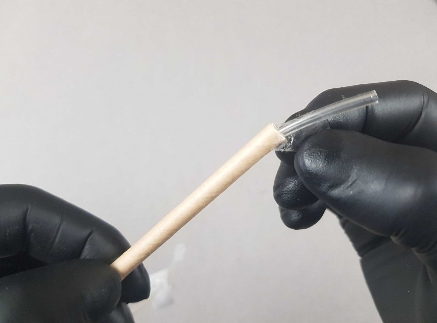
Insert a small plastic Connector into the end of the tubing, below the Tube Clamp.
Make sure the tubing is over the Connector.
Info
The result should look the same as the picture.
Remove the cardboard protector from the Fluidic Path.
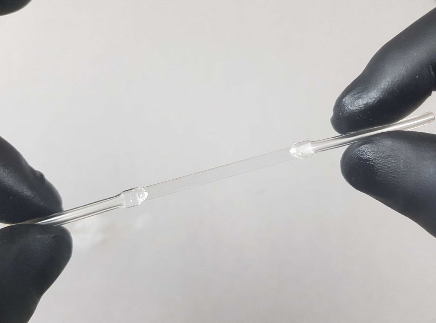
Warning
A reminder, the glass part of the Fluidic Path is very delicate. Please try not to touch it.
Place another Connector at the end of the tubing.
The result should be the same as the picture.
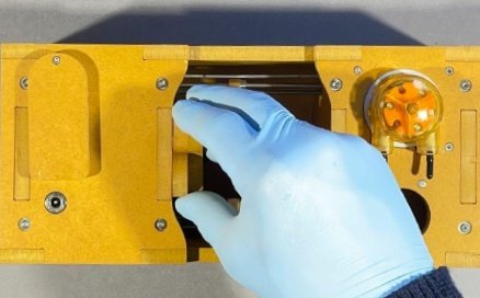
⚠ Gently place the Fluidic Path in the designated indentation on Part F.
Warning
Do not touch the glass.
- You may have to slightly stretch the tubing to get the Fluidic Path into position.
- The result should be the same as the picture.
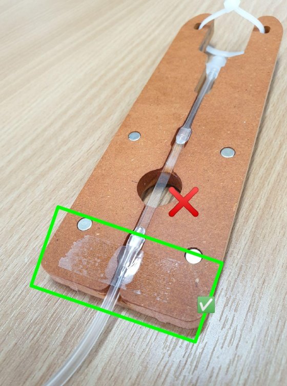
If you have tape available, place a small piece at the the bottom of Part F so that the tubing remains fixed in its position.
Avoid placing tape over the glass.
Info
The result should be similar to the picture.
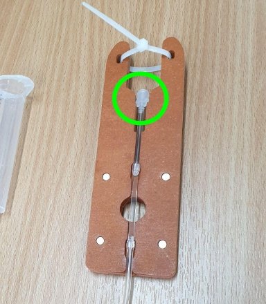
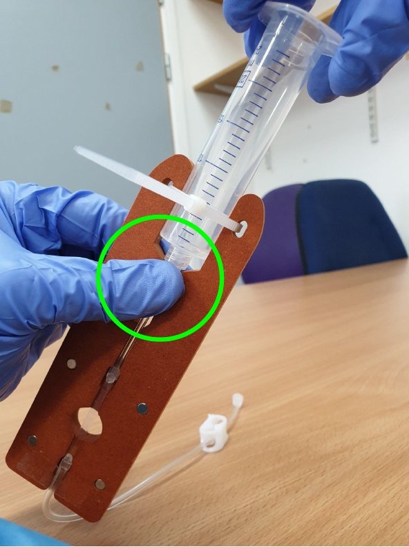
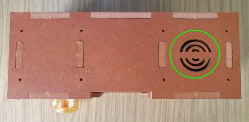
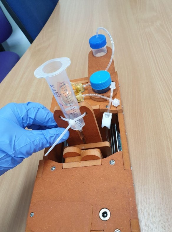
To insert the syringe, place finger and thumb either side of part F where green circle is located. This ensures the tubing does not rotate while you twist the syringe into position in a clockwise direction.
Info
The result should be similar to the picture.
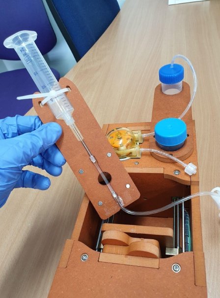
- Place the Fluidic Path into position between the mount and the Peristaltic Pump.
- Connect the magnets to face each other.
The result should look the same as the pictures.
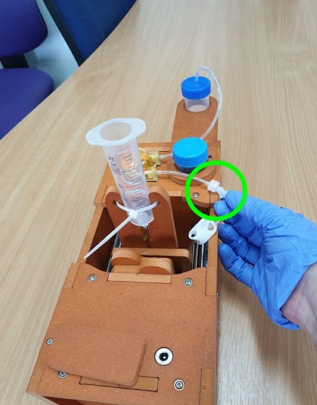
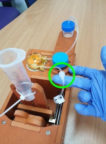
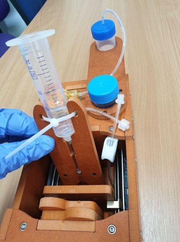
- 🟢 Connect the Fluidic Path to the Peristaltic Pump by twisting the two connectors together.
- The result should be the same as the picture.
Build complete! 💯 💫🔗
Next steps🔗
Next, you will need to set up the PlanktoScope software on the micro-SD card of your PlanktoScope's Raspberry Pi.